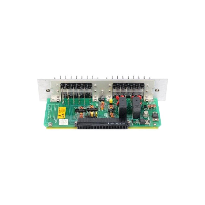
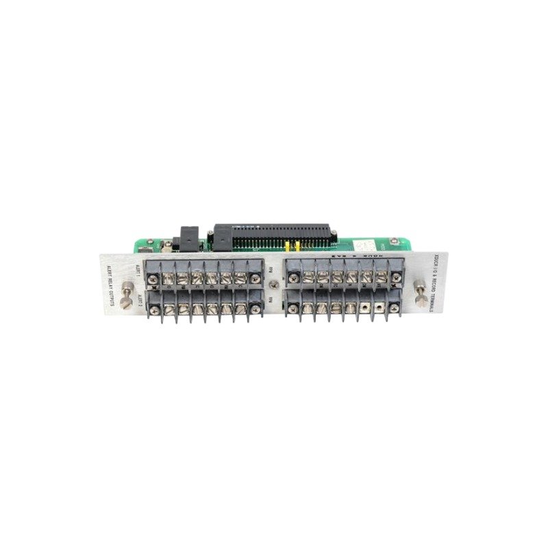
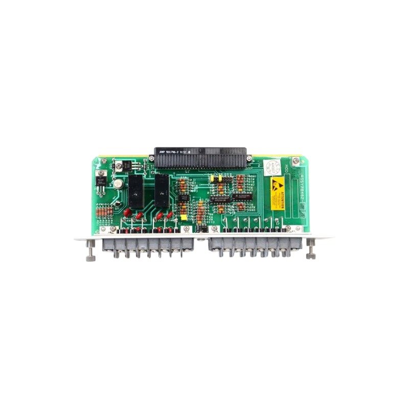
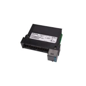
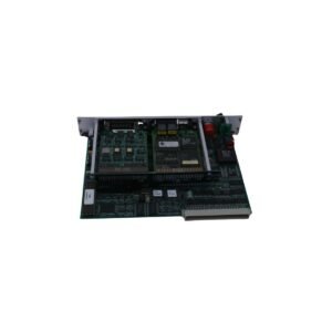
Configured for discrete alarm routing and instrumentation interlocking within machinery protection racks, the Bently Nevada 84140-01 (Bently Nevada 84140 Relay Card) provides direct physical/electrical execution. The device accepts logic states generated by the monitor modules via the system backplane and translates them into physical contact closures to control external trip circuits.
Suffix Breakdown & Model Matrix
Parameter
Specification
Base Model
84140 Signal Input Relay Card Platform
Suffix Option (-01)
Standard multi-channel relay array configuration with factory-default terminal block matching
Hardware Specifications
Parameter
Specification
Model
84140-01
Brand
Bently Nevada
Origin
USA
Weight
0.8 kg
Dimensions
16.0 x 16.0 x 12.0 cm
Operating Temp
0 deg C to +70 deg C
Power Consumption
Supported directly via the internal rack backplane circuit
Storage Temp
-40 deg C to +85 deg C
Relay Outputs
Multi-channel electromechanical dry contacts
Enclosure Matching
Form factor aligned with designated monitoring system slots
Rotor Dynamics and Cross-Talk Suppression Integration
This discrete control card routes voting logic metrics generated during high-velocity rotor dynamics transitions. Because proximity probes require tight eddy-current probe scaling to track shaft centerline motion, the associated backplane logic processes these dynamic inputs concurrently. The hardware paths are isolated to achieve cross-talk suppression between the adjacent switching paths, ensuring that high-frequency electromagnetic noise or inductive surges from external trip coils do not corrupt the sensitive analog transducer signals.
Frequently Asked Questions
Q: Can the 84140-01 card be removed from the rack chassis while the machinery protection system is fully powered?
A: No. Removing or inserting the card while power is applied can induce electrical transients across the backplane bus, causing accidental trip signals or hardware faults in adjacent monitoring modules.
Q: What is the primary indicator of contact degradation on this module?
A: An increase in contact resistance across the dry terminals or intermittent continuity during commanded state transitions indicates mechanical or electrical wear on the relay elements.
Field Installation Guidelines
Chassis Insertion and Seating Sequence: Align the module straight within the designated rear chassis slots. Push firmly until the backplane connectors seat completely, then tighten the securing screws to establish structural ground.
Terminal Routing Standards: Route external control and emergency shutdown wiring through separate wire ways. Keep these high-current paths isolated from low-voltage transducer coaxial cables to prevent electromagnetic coupling.
Shield Maintenance Topology: Terminate field cable shields at the rack chassis common ground terminal bar only. Ensure the field end of the shield remains ungrounded to prevent ambient ground loop current paths.
Additional information
Weight
0.80 kg
Dimensions
80 × 70 × 75 mm
0.0
Average Rating
Rated
(0 Reviews)
Rated
0%
Rated
0%
Rated
0%
Rated
0%
Rated
0%
Be the first to review “Bently Nevada 84140-01 Relay Card” Cancel reply











0.0 Average Rating Rated (0 Reviews)