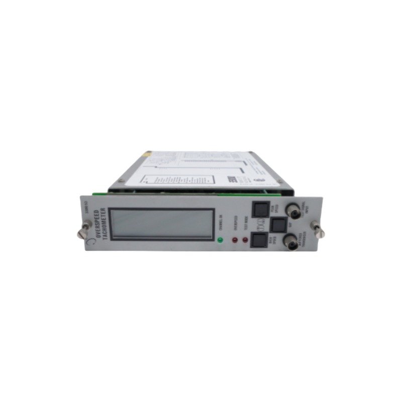
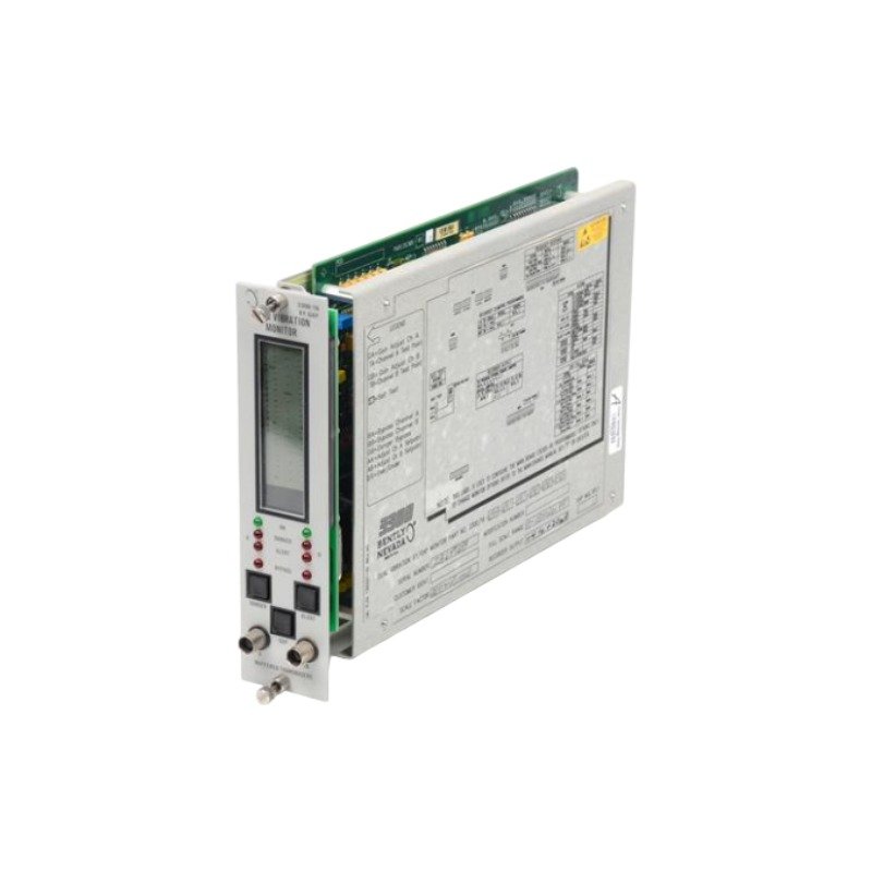
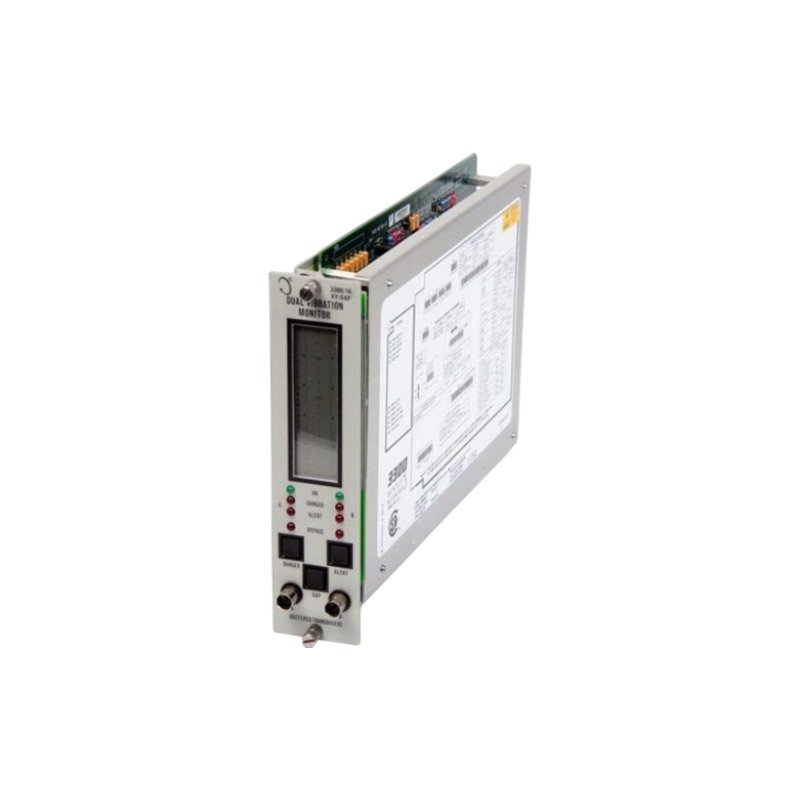
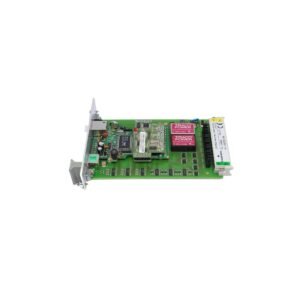
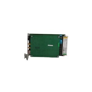
The Bently Nevada 81410-01 is a 3300/35 series dual-channel vibration monitor board supporting proximity probes and velocity transducers. Brand New, Original Stock, Global Shipping.
Configured for continuous radial, axial, and casing vibration measurements in machinery protection networks, the Bently Nevada 81410-01 (81410-01 Dual Vibration Monitor Board) provides direct physical and electrical execution. Specifically, this rack-mounted module processes dynamic analog voltage signals from two independent proximity probes or velocity transducers. Because the internal circuitry executes programmable protection logic directly on the board, the unit monitors asset parameters according to strict API 670 machinery protection compliance criteria. Consequently, this processing pathway delivers raw sensor data straight to front-panel buffered outputs while driving high and danger alarm relays to preserve plant uptime.
This dual vibration monitor board maintains absolute signal integrity by managing the specific electrical boundaries necessary for precise eddy-current probe scaling. The board hardware conducts automated gap voltage validation (-10 VDC targets) across both proximity loops to verify the baseline distance before evaluating dynamic shaft motion. Because the module tracks rapid rotor dynamics deviations during machine startup cycles, its layout integrates comprehensive cross-talk suppression paths across the multi-channel interface. As a result, this filtering isolates adjacent high-frequency carrier waveforms, preventing parasitic noise injection from distorting the low-voltage analog inputs.
Frequently Asked Questions
Q: How do the front-panel buffered transducer outputs interact with the live machinery protection loop?
A: The buffered outputs utilize internal op-amp isolation circuits that isolate test equipment from the primary measurement loop. Therefore, technicians can perform real-time wave-form checks or spectrum analysis without disrupting active protection signals.
Q: Can a single 81410-01 module track a proximity probe on channel one and a velocity transducer on channel two simultaneously?
A: Yes, the dual-channel design allows individual channel configuration. Technicians can program alert and danger setpoints independently for each path to accommodate mismatched sensor inputs on the same physical asset.
Q: What action does the monitoring board execute if an interconnected field cable undergoes a short-circuit failure?
A: The board detects the anomalous loop voltage drop and immediately drives the affected channel into a NOT OK fault state. This hardware response blocks the channel from tripping the high/danger relays, avoiding a false shutdown command.
Field Installation Guidelines
Mounting Mechanics: Insert the compact module frame straight into the assigned slot layout of the 3300/35 rack enclosure. Next, fasten all rear connector panel interfaces securely to ensure stable mechanical connectivity against ongoing structural vibration.
Shielding Requirements: Terminate the braided sensor cables at the designated instrument ground rail. Furthermore, run the ground shield continuously from the field sensor junction box to the rack common point, keeping the field-side housing completely ungrounded to eliminate loop currents.
Wiring Separations: Separate all incoming transducer lines from auxiliary high-voltage AC utility distribution drops or noisy motor drive feeds. Maintain a clear space barrier of at least 300 mm to protect the low-voltage millivolt signals from inductive noise.
Thermal Management: Verify that cabinet cooling fans provide adequate airflow through the internal module gaps. Additionally, measure ambient conditions to confirm that the local temperature around the board remains inside the designated -35 deg C to +65 deg C operating envelope.
Additional information
Weight
0.55 kg
Dimensions
64 × 72 × 73 mm
0.0
Average Rating
Rated
(0 Reviews)
Rated
0%
Rated
0%
Rated
0%
Rated
0%
Rated
0%
Be the first to review “Bently Nevada 81410-01 Dual Vibration Monitor Board” Cancel reply











0.0 Average Rating Rated (0 Reviews)