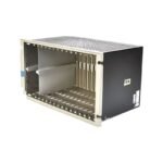
Bently Nevada 3500/05-01-01-00-00-00 full-size 19-inch panel mount instrument rack chassis. Brand New factory stock with comprehensive global shipping options.
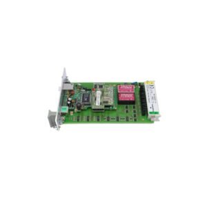
The Bently Nevada 3500/05-01-01-00-00-00, also cataloged as the 3500/05 14-Slot Panel Mount Chassis, operates as a dedicated hardware component for high-speed backplane data communication and distributive DC power allocation within the 3500 Machinery Protection System. This specific full-size unit supplies structural mounting and electronic pathways for machinery condition monitors, power modules, and transient data interfaces. It establishes the physical interface required to execute real-time machine safety logic across multi-channel turbomachinery installations.
Suffix Breakdown & Model Matrix
This exact hardware configuration conforms to the following structural factory option selections:
01 (Rack Size Option): Designates a 19-inch EIA Full-Size Rack layout containing 14 operational module slots alongside two dedicated leftmost power slots.
01 (Mounting Option): Configures the physical structure for a Panel Mount setup, utilizing external clamps to fasten the unit into a rectangular panel cutout.
00 (Agency Approval Option): Specifies no hazardous area approvals; restricted to safe, non-hazardous industrial environments.
00 (Reserved Option): Factory default reserved parameter containing no special field additions.
00 (European Compliance Option): Specifies standard basic manufacturing configuration without specific post-production regional marking kits.
Hardware Specifications
Parameter
Specification
Model
3500/05-01-01-00-00-00
Brand
Bently Nevada
Origin
United States
Weight
7.50 kg
Dimensions
482.60 mm x 265.94 mm x 246.38 mm
Operating Temp
-20 to +65 deg C
Power Consumption
Passive backplane; actual power distribution determined by active modular load
Layout Type
19-inch EIA industrial footprint
Slot Configuration
2 Power supply positions (left) + 14 instrumentation slots
I/O Access Route
Rear-facing terminal access for main cards and I/O modules
Rotor Dynamics and Eddy-Current Probe Scaling
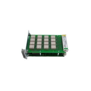
The multi-layer backplane circuitry embedded within this specific chassis layout enforces physical trace shielding boundaries to maximize cross-talk suppression. These internal ground planes prevent high-frequency oscillator signals from bleeding between adjacent radial vibration monitor cards. By containing electromagnetic interference, the backplane maintains a precise loop environment to validate gap voltage validation (-10 VDC targets) across 3300 XL proximity sensor circuits, preserving raw waveform data fidelity for advanced rotor dynamics diagnostic software.
Frequently Asked Questions
Q: How are field wiring connections accessed on this specific panel-mount configuration?
A: Field sensor wiring and individual input/output hardware modules mount directly to the rear of the 3500/05 backplane structure. This arrangement requires physical rear access to the instrument panel during field installation, routine diagnostic monitoring, and terminal termination maintenance.
Q: Can single-slot monitor modules be added while the backplane is powered by dual 3500/15 units?
A: Yes. The structural backplane incorporates pre-aligned grounding and power pins of varied physical lengths. This mechanical progression guarantees that logic grounds make contact before active power traces during hot-swap actions, which isolates adjacent channels from voltage dips.
Field Installation Guidelines
Shielding and Grounding Standards: Secure a heavy-gauge copper grounding strap from the primary rack earth stud directly to the plant instrumentation master ground. Terminate all incoming eddy-current probe shield drain wires at the rear terminal block ground screws to avoid noise injection into the backplane.
Panel Cutout Tolerances: Ensure the rectangular panel mounting cutout adheres strictly to the factory specified dimensional boundary limits. Use all provided side-mounting retention clamps to secure a rigid mechanical seal, minimizing localized structural resonance from transferring onto the internal monitor cards.
Power Trace Isolation: Route primary AC or high-voltage DC supply line conduit separately from the low-voltage sensor input wiring trays. This separate routing method minimizes external induced magnetic fields from corrupting low-level vibration signals.
Additional information
Weight
7.5 kg
Dimensions
820 × 680 × 460 mm
0.0
Average Rating
Rated
(0 Reviews)
Rated
0%
Rated
0%
Rated
0%
Rated
0%
Rated
0%
Be the first to review “Bently Nevada 3500/05-01-01-00-00-00 System Rack” Cancel reply


0.0 Average Rating Rated (0 Reviews)