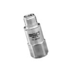
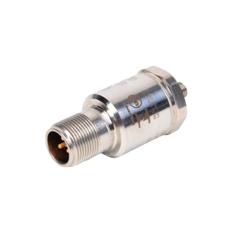
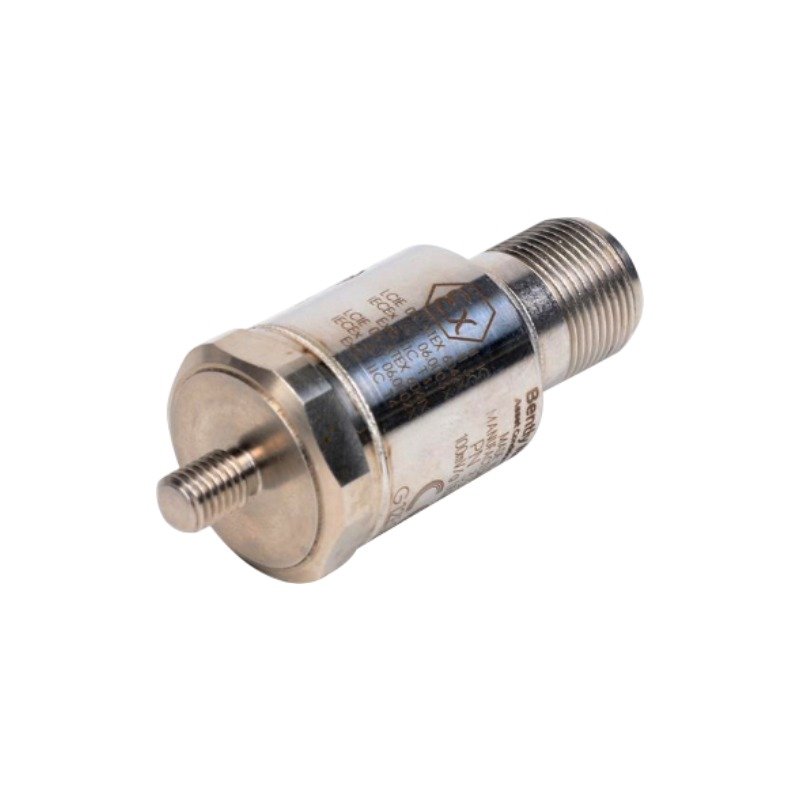
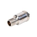
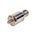
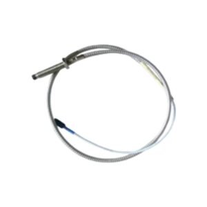
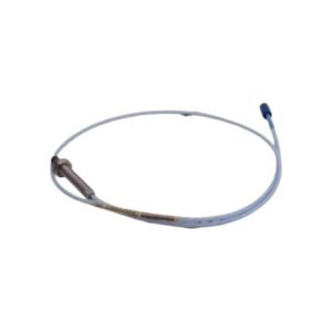
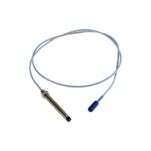
Configured for critical casing acceleration measurements in machinery protection platforms, the Bently Nevada 330400-01-05 (330400 Accelerometer Transducer) provides direct physical/electrical execution.
Suffix Breakdown & Model Matrix
330400: Accelerometer Acceleration Transducer
01: 1/4-28 UNF integral stud mounting thread option
05: Multiple international agency approvals (CSA, ATEX, IECEx)
Hardware Specifications
Parameter
Specification
Model
330400-01-05
Brand
Bently Nevada
Origin
United States
Weight
0.099 kg
Dimensions
23.0 mm (Diameter) x 59.0 mm (Height)
Operating Temp
-55 to +121 deg C
Power Consumption
2 mA nominal at -24 VDC
Sensitivity
10.2 mV/m/s2 (100 mV/g) ±5%
Amplitude Range
490 m/s2 (50 g) peak overall
Frequency Response
10 Hz to 15 kHz (±3 dB)
Mounted Resonant Frequency
Greater than 30 kHz
Eddy-Current Probe Scaling and Rotor Dynamics Correlation
Consequently, the piezoelectric internal sensor elements generate an electrostatic charge proportional to casing acceleration, thereby driving high-frequency vibration signal transmission. To ensure comprehensive diagnostic monitoring, engineers utilize this casing accelerometer in conjunction with Bently Nevada proximity probe systems. Specifically, this configuration allows the monitoring system to correlate casing acceleration trends with shaft relative vibration. Furthermore, the integration of casing vibration data provides deeper visibility into high-frequency mechanics such as gear mesh signatures and rotor dynamics anomalies. As a result, the monitoring platform resolves complex machinery malfunctions by pairing direct rotor measurements with casing excitation characteristics.
Frequently Asked Questions
Q: Does the 330400-01-05 accelerometer isolate its electrical signal from physical casing ground?
A: Yes. Specifically, the internal transducer design incorporates full case isolation, therefore preventing common ground loops and maintaining signal integrity even when mounted directly to standard machine casings.
Q: What are the primary physical constraints on the interconnect cable run?
A: The transducer supports a maximum raw cable run of 305 meters (1000 feet) between the sensor head and the monitoring system. However, the technician must use 3-conductor shielded cabling to achieve this run without experiencing signal degradation or noise interference.
Field Installation Guidelines
First, prepare the machine casing surface to a flatness specification of 32 microinch rms. Thereafter, apply a light lubricant film to the mating surface to optimize high-frequency acoustic transmission.
Second, torque the integral 1/4-28 UNF mounting stud precisely to 4.1 N-m (3.0 ft-lb). This action ensures rigid coupling to the bearing housing, thus preventing false vibration peaks caused by a loose mounting resonance.
Third, isolate the 3-pin MIL-C-5015 connector socket by wrapping the terminal assembly with a fluorosilicone boot or self-fusing silicone tape. Consequently, this precaution prevents moisture entry and ensures the continuous IP 68 rating of the sensor head.
Finally, route the interconnecting cable along the machine frame using protective conduit or cable clamps. Consequently, this step avoids excessive mechanical strain or whip on the connector interface.
Additional information
Weight
0.10 kg
Dimensions
63 × 25 × 23 mm
0.0
Average Rating
Rated
(0 Reviews)
Rated
0%
Rated
0%
Rated
0%
Rated
0%
Rated
0%
Be the first to review “Bently Nevada 330400-01-05 Accelerometer Acceleration Transducer” Cancel reply












0.0 Average Rating Rated (0 Reviews)