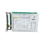
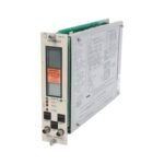
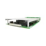
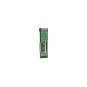
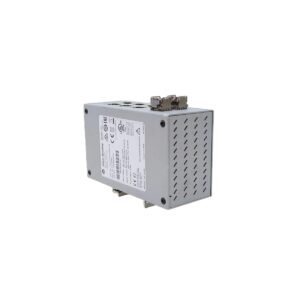
Configured for rotative speed monitoring and acceleration measurement in 3300 Machinery Protection System racks, the Bently Nevada 3300/50 (3300/50 Tachometer Monitor) provides direct physical/electrical execution.
Suffix Breakdown & Model Matrix
The 3300/50 product code utilizes a standard four-part variable matrix (3300/50-AA-BB-CC-DD) to define specific hardware configurations:
AA (Tachometer Type): 01 = Dual Setpoint Tachometer, 02 = Zero Speed Tachometer, 03 = Rotor Acceleration Tachometer.
BB (Alert Relays): 00 = None, 01 = 5 A Epoxy Sealed, 02 = 5 A Hermetically Sealed.
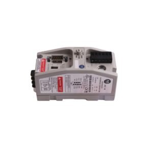
CC (Agency Approval): 00 = Not Required, 01 = CSA, 02 = BASEEFA, 03 = Factory Mutual (FM).
+4 to +20 mA, 0 to -10 VDC, or +1 to +5 VDC (User-programmable)
Gap Voltage Validation and Transducer Supply Regulation
The module interfaces with front-panel coaxial connectors to provide independent buffered transducer outputs. Consequently, technicians perform gap voltage validation (-10 VDC targets) directly on the front panel without disturbing active rack backplane wiring. The internal power supply stage regulates transducer supply lines, maintaining precise voltage stability to support external eddy-current probe scaling. Furthermore, embedded phase-locked filtering circuits perform cross-talk suppression, preventing inductive pulse interference from high-voltage speed sensors from corrupting adjacent channels during transient rotor dynamics analysis.
Frequently Asked Questions
Q: Why does the 3300/50 Tachometer Monitor accept inputs from two distinct speed transducers?
A: The hardware utilizes two transducer inputs to implement internal voting logic. This internal comparison minimizes false speed alarms or zero-speed declarations if a single magnetic pickup or proximity probe undergoes a hardware fault.
Q: Can the 3300/50 monitor execute overspeed trip safety control functions?
A: No, the 3300/50 internal circuit architecture lacks the necessary protective redundancy and fast execution response required for overspeed trip execution. Consequently, plants must employ separate dedicated emergency overspeed shutdown systems for control-loop actions.
Field Installation Guidelines
Chassis Slot Placement: Install the 3300/50 card in any universal slot from Position 3 to Position 14. Slots 1 and 2 remain strictly reserved for the system power supply and system monitor.
Wiring Interface Termination: Connect the magnetic pickup or proximity probe leads to the rear terminal blocks using shielded twisted-pair cables. Tighten terminal connections to a maximum torque value of 0.56 N-m.
Shield Continuity Management: Ground the cable shields explicitly at the main system rack ground bus bar. Do not connect the shield at the field sensor enclosure, avoiding ground loop generation.
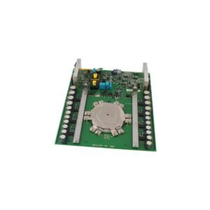
Jumper Configuration Access: Adjust the internal slide switches and plug-in jumpers on the circuit board to set the correct full-scale range and recorder output types before sliding the module into the rack chassis.
Additional information
Weight
1.1 kg
Dimensions
60 × 120 × 60 mm
0.0
Average Rating
Rated
(0 Reviews)
Rated
0%
Rated
0%
Rated
0%
Rated
0%
Rated
0%
Be the first to review “Bently Nevada 3300/50 3300 Series Tachometer Monitor Module” Cancel reply


0.0 Average Rating Rated (0 Reviews)