Get the Bently Nevada 3300/16-14-01-01-00-00-00 XY/Gap module. Brand New factory surplus from Original Stock. Global Shipping options secure quick deployment.
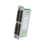
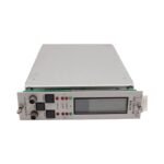
The Bently Nevada 3300/16-14-01-01-00-00-00, also cataloged as the 3300/16 XY/Gap Dual Vibration Monitor, operates as a dedicated hardware component for continuous radial vibration and average shaft position processing within 3300 Machinery Protection System platforms.
Suffix Breakdown & Model Matrix
Option Selection
Code Description
Technical Execution
A: 14
0-10 mils peak-to-peak
Tracks imperial vibration displacement across a designated 10 mils scale range.
Drives direct circuit interruptions via hardware Alert and Danger relay contacts.
D: 00
No Agency Approvals
Complies with basic manufacturer standards without localized non-incendive certifications.
E: 00
No Safety Barriers
Establishes standard un-barriered terminations without internal galvanic isolation blocks.
F: 00
No Trip Multiply
Disables external scale factoring for machine startup validation loops.
G: 00
Standard Configuration
Retains standard factory firmware and default hardware tuning parameters.
Hardware Specifications
Parameter
Specification
Model
3300/16-14-01-01-00-00-00
Brand
Bently Nevada
Origin
USA
Weight
1.0 kg
Dimensions
51.0 mm x 229.0 mm x 115.0 mm
Operating Temp
0 deg C to 65 deg C
Power Consumption
2.0 W (Nominal)
Display Technology
63-segment non-multiplexed LCD with vertical bar graphs
Eddy-Current Probe Scaling and Rotor Dynamics Processing
To maintain strict tracking accuracy over complex rotor dynamics, the internal signal conditioning circuitry interfaces directly with external proximity probe drivers. Consequently, this architecture requires precise calibration matching the 200 mV/mil transducer scaling curve. The microprocessor continuously digitizes the incoming dynamic waveform to calculate overall peak-to-peak displacement, while simultaneously extracting the DC bias voltage component. Furthermore, this voltage evaluation executes ongoing gap voltage validation down to a target -10 VDC baseline, confirming correct sensor positioning before applying threshold alarm logic. Specifically, the integrated filter networks provide optimal cross-talk suppression between adjacent channels, preventing high-frequency noise from corrupting the raw analog metrics.
Frequently Asked Questions
Q: How does the 3300/16 manage independent channel operation if one proximity probe fails?
A: When the monitor detects an out-of-range sensor voltage, it immediately triggers a NOT OK status for that specific channel. Subsequently, the internal logic de-energizes the channel OK relay and illuminates the front panel fault LED, yet it maintains completely independent alarm processing on the remaining functional channel.
Q: What are the electrical parameters of the programmable recorder outputs on this card?
A: Technicians can jumper-configure the rear-panel recorder terminals to output +4 to +20 mA, 0 to -10 VDC, or +1 to +5 VDC. These signals map proportionally to the 0-10 mils full-scale measurement range, enabling direct interface tracking into external DCS or PLC systems.
Field Installation Guidelines
Technicians must slide the 3300/16 card into the designated backplane slot of the instrument rack until the rear connectors interface securely with the mating pins. Next, fasten the front panel thumb screws to ground the aluminum chassis plate firmly to the structural framework. When completing the field wiring on the rear terminal blocks, ensure that the twin-axial or coaxial shield lines route directly to the dedicated chassis ground terminals. To prevent radio frequency interference from inducing noise onto the 200 mV/mil analog signal, avoid routing sensor input cabling adjacent to high-voltage AC lines. Finally, verify that the internal power supply configuration yields a stable -24 VDC voltage level to drive the external Proximitor sensors.
Additional information
Weight
1 kg
Dimensions
320 × 120 × 130 mm
0.0
Average Rating
Rated
(0 Reviews)
Rated
0%
Rated
0%
Rated
0%
Rated
0%
Rated
0%
Be the first to review “Bently Nevada 3300/16-14-01-01-00-00-00 XY/Gap Dual Vibration Monitor” Cancel reply


0.0 Average Rating Rated (0 Reviews)