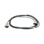
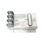
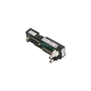
The Bently Nevada 24583-03, also cataloged as the 24583-03 Shielded Extension Cable, serves as the primary 24583 hardware link utilized to execute low-attenuation signal transmission between an 8mm proximity probe and a matching 3300 XL Proximitor Sensor across machinery protection platforms.
Suffix Breakdown & Model Matrix
Option Code
Parameter Slot
Technical Specification
03
Total Length Option
3.0 m (9.8 ft) total cable length
Hardware Specifications
Parameter
Specification
Model
24583-03
Brand
Bently Nevada
Origin
United States
Weight
0.14 kg
Dimensions
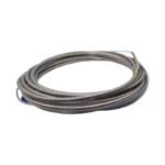
3.0 m length, 75 Ohm coaxial architecture
Operating Temp
-51 deg C to +177 deg C
Capacitance
60 pF/m nominal
Material
FEP jacket with coaxial braided shield
Connector Type
Miniature coaxial male and female ends
Rotor Dynamics and Cross-Talk Suppression
The 75 Ohm coaxial link bridges the gap between the field-mounted eddy-current probe tip and the backend signal conditioning instrumentation. Consequently, the cable physical length and capacitance parameters are precisely matched to the system tuning to preserve accurate eddy-current probe scaling matrices. During operations, tracking loops pass static and dynamic voltage signals through the core conductor to perform precise gap voltage validation against -10 VDC targets. Because extension cable runs frequently span dense layout cable trays, the integrated FEP jacket and high-density coaxial braid maximize active cross-talk suppression, preventing noise from corrupting high-frequency transient waveforms used in evaluating rotor dynamics.
Frequently Asked Questions
Q: Can the 24583-03 cable be cut and spliced in the field to adjust its physical length?
A: No. The physical length is an integral part of the transducer system electrical calibration matrix. Cutting or altering the length shifts system capacitance, which invalidates the 200 mV/mil scaling factor.
Q: What indicates an insulation or shielding failure within the extension cable assembly?
A: An insulation failure typically causes erratic shifts in the DC bias output. Consequently, the monitor module will flag a transducer fault during regular gap voltage validation checks.
Field Installation Guidelines
Connector Protection Shells: Encase the connection point between the probe lead and the extension cable inside a self-fusing silicone sleeve or connector protector. Consequently, this measure isolates the coaxial outer ring from making grounding contact with the machinery casing.
Bend Radius Constraints: Maintain a minimum structural bend radius of 25 mm along the extension cable run. As a result, this prevents internal dielectric kinking and safeguards the integrity of the coaxial shield braid.
Conduit Segregation Protocol: Route the extension cable inside dedicated, grounded steel conduit pathways. Additionally, ensure these runs remain completely separated from high-voltage AC motor lines to eliminate external inductive coupling.
Additional information
Weight
0.14 kg
Dimensions
50 × 26 × 20 mm
0.0
Average Rating
Rated
(0 Reviews)
Rated
0%
Rated
0%
Rated
0%
Rated
0%
Rated
0%
Be the first to review “Bently Nevada 24583-03 3300 XL Proximitor Sensor Extension Cable” Cancel reply


0.0 Average Rating Rated (0 Reviews)