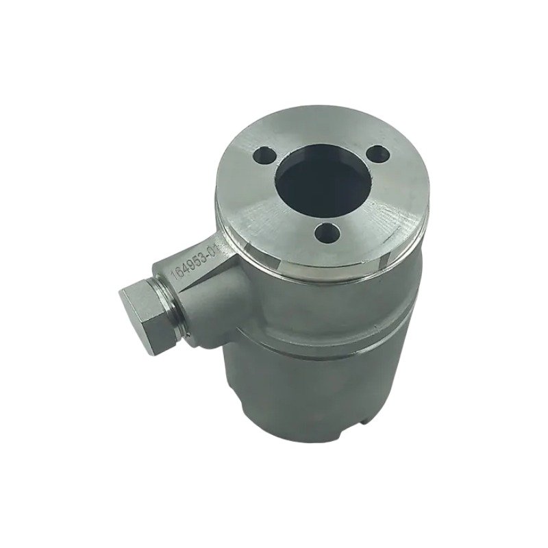
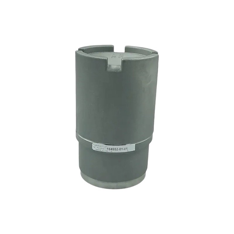
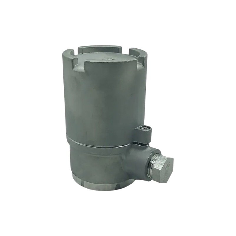
The Bently Nevada 164952-01-01 is a Feraloy metal alloy accelerometer mounting kit for industrial vibration systems. Brand New, Original Stock, Global Shipping.
Configured for stable sensor coupling and repeatable installation in diagnostic networks, the Bently Nevada 164952-01-01 (164952-01-01 Accelerometer Mounting Kit) provides direct physical/electrical execution. Specifically, this mechanical enclosure framework fixes the physical position of vibration sensors relative to rotating machinery casings, thereby enabling uncorrupted transmission of raw high-frequency acceleration signals. Furthermore, the industrial housing assembly institutes a sealed protective barrier around the transducer connection point, which facilitates strict compliance with API 670 machinery protection installation metrics.
Hardware Specifications
Parameter
Specification
Model
164952-01-01
Brand
Bently Nevada
Origin
USA
Weight
820 g
Dimensions
Compatible with standard industrial accelerometer footprints
Operating Temp
Compatible with standard rotating machinery industrial conditions
Power Consumption
None (Mechanical accessory)
Base Material
Corrosion-resistant metal alloy (Feraloy)
Mounting Hardware
Base housing, flat cover, 3 x 1/4-20 UNC x 0.62 in screws, lock washers, O-ring, gasket, cable grip
Conduit Compatibility
12 mm (1/2 in) flexible or rigid conduit
Sealing & Grounding
Integrated gasket and O-ring sealing; structural grounding provisions included
Protection Rating
Water-tight and dust-resistant
Machinery Monitoring and TSI Characteristics
This accelerometer mounting kit actively preserves the baseline path required for accurate eddy-current probe scaling and seismic transducer execution because its rigid design prevents mechanical resonance amplification. Consequently, the flat, machined base interface eliminates structural flexing, which allows accurate gap voltage validation (-10 VDC targets) on proximity loops and precise waveform capture on seismic paths during continuous monitoring loops. By securing the sensor coupling against high-frequency vibration, the hardware allows diagnostic processors to track true rotor dynamics during transient machine startup and shutdown phases. Additionally, the integrated grounding provisions ensure maximum cross-talk suppression by preventing common-mode noise voltages from coupling into low-amplitude analog acceleration loop circuits via the machine frame.
Frequently Asked Questions
Q: Does the mechanical housing structure limit or damp the high-frequency response matrix of the enclosed accelerometer?
A: The rigid corrosion-resistant metal alloy structure maintains a tight, high-stiffness mechanical coupling with the machine casing. Additionally, executing the spot-face preparation correctly ensures uniform transmission of high-frequency vibration up to the sensor’s design limits without signal damping.
Q: What action should technicians take regarding the included O-ring and gasket during standard maintenance intervals?
A: Technicians must inspect the O-ring and gasket for deformation or environmental degradation during scheduled machinery downtime. Replace damaged sealing components immediately to maintain the water-tight and dust-resistant barrier.
Q: Can this mounting kit accommodate standard alternative configurations such as dome covers or extension accessories?
A: The modular layout accepts optional accessories, including deep dome covers and specialized extension kits, to house larger sensor heads or customized wiring assemblies without modifying the core base footprint.
Field Installation Guidelines
Mounting Mechanics: Spot-face the machinery surface completely prior to mounting to achieve a flat, uniform contact area. Secure the base housing using the three 1/4-20 UNC x 0.62 in screws along with their matching lock washers, tightening them to standard torque parameters to prevent mechanical loosening.
Shielding Requirements: Utilize the integrated grounding provisions to establish electrical continuity between the enclosure body and the central machine frame ground. Ensure the internal cable shields are isolated from the mounting box to prevent loop currents from generating signal noise.
Wiring Separations: Thread the sensor output cable through the integrated 12 mm (1/2 in) flexible or rigid conduit path. Route the conduit run away from parallel high-voltage AC electrical links or active variable frequency drive wiring paths.
Thermal Management: Verify that the localized operational temperature remains within standard rotating machinery environment parameters. Ensure that the cable grip is tightened fully around the jacket to prevent moisture or dust ingress from compromising internal connections.
Additional information
Weight
8.20 kg
Dimensions
98 × 85 × 77 mm
0.0
Average Rating
Rated
(0 Reviews)
Rated
0%
Rated
0%
Rated
0%
Rated
0%
Rated
0%
Be the first to review “Bently Nevada 164952-01-01 Accelerometer Mounting Kit” Cancel reply











0.0 Average Rating Rated (0 Reviews)