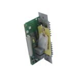
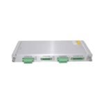
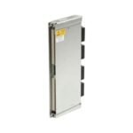
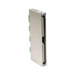
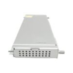
The Bently Nevada 133827-02, also cataloged as the 133827-02 3500/61 RTD/TC Non-Isolated I/O Module with External Terminations, operates as a dedicated hardware component for thermal tracking and sensor signal routing within 3500 Series machinery protection systems. Specifically, this rack-mounted rear I/O card accepts analog data from external Resistance Temperature Detectors (RTD) and Thermocouples (TC). Consequently, the hardwired connection passes critical process variables directly to the front-panel temperature monitor for alarm evaluation. Furthermore, the specialized external termination layout facilitates efficient wire mapping inside remote junction boxes without expanding the physical footprint of the main monitoring chassis.
Hardware Specifications
Parameter
Specification
Model
133827-02
Brand
Bently Nevada
Origin
United States
Weight
0.41 kg
Dimensions
241 mm x 25 mm x 102 mm
Operating Temp
-30 deg C to +65 deg C
Power Consumption
1.8 W nominal consumption
Sensor Input Types
Pt100, Cu10, Type J, Type K, Type T (all non-isolated)
Mounting Location
Rear slot position of 3500/61 monitor card
Interface Target
External Termination (ET) blocks via multi-pin cable
Eddy-Current Probe Scaling and Mechanical Validation
Because the Bently Nevada 133827-02 module handles sensitive millivolt and ohm-level sensor inputs, its structural ground isolation framework directly protects the signal integrity of nearby vibration monitoring loops. Improper grounding or common-mode voltage leaks on temperature loops can introduce severe electrical noise into the backplane, which eventually disrupts the calibrated eddy-current probe scaling and sensor linearity of adjacent proximity channels. To counter this risk, the card separates the digital backplane ground paths from the field transducer analog returns, maintaining high cross-talk suppression.
During comprehensive system validation routines, field instrument engineers balance thermal data analysis with mechanical validation processes. While proximity probe systems undergo gap voltage validation to maintain a stable -10 VDC baseline, temperature inputs rely on exact continuity and cold junction reference matching. When technicians configure the associated 3500/61 monitor for a Triple Modular Redundant (TMR) safety layout, the I/O module paths route signals in parallel groups of three. This setup ensures fail-safe state execution through hardware-driven voting logic, preventing any single-point open-circuit or short-circuit fault from causing false trips or corrupting the online rotor dynamics monitoring.
Frequently Asked Questions
Q: Can field technicians execute hot-swap replacement on the 133827-02 module while the monitor rack stays energized?
A: No, you must de-energize the monitor slot or place the complete protection loop into an active bypass state before extracting the rear I/O module. Removing the card under live backplane electrical loads interrupts the sensor loop currents, which instantly causes sensor fault statuses and can trip downstream machinery protection logic.
Q: How does this non-isolated version manage high ground potential differences across long field wire runs?
A: This module utilizes a non-isolated architecture, meaning it features no channel-to-channel galvanic isolation. Consequently, you must ensure that all field-mounted thermocouples are ungrounded types, and you must verify that the field sensor leads do not exceed a common-mode voltage threshold of 2 V relative to the monitor rack earth ground.
Field Installation Guidelines
Confirm that the 3500 chassis power supply is completely switched off and that the corresponding channel group is bypassed before sliding the I/O card into the rear backplane slot.
Route the heavy multi-pin external termination cable between the 133827-02 rear connector and the external termination block carefully, maintaining a minimum bend radius of 75 mm along the cable run.
Verify that all thermocouple extension wires match the exact alloy type (e.g., Type J or Type K) of the physical field sensor to prevent parasitic junctions from distorting the temperature calculations.
Tighten the multi-pin D-sub retention screws manually with a flathead screwdriver to a maximum torque of 0.4 Nm to lock the physical interface against local machinery vibrations.
Separate the low-voltage RTD and thermocouple sensor input cables from high-voltage AC electrical distribution lines by a minimum of 300 mm within the cable trays to prevent inductive noise injection.
Additional information
Weight
0.41 kg
Dimensions
70 × 210 × 60 mm
0.0
Average Rating
Rated
(0 Reviews)
Rated
0%
Rated
0%
Rated
0%
Rated
0%
Rated
0%
Be the first to review “Bently Nevada 133827-02 3500/61 RTD/TC Temperature I/O Module” Cancel reply


0.0 Average Rating Rated (0 Reviews)