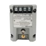
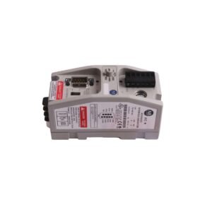
The Bently Nevada 102618-01 operates as a critical infrastructure module within legacy Bently Nevada monitoring frameworks (such as the 3300 series System Monitor interfaces). It serves as the physical and electrical bridge that handles baseline operating power routing and field data interface configurations for the rack’s centralized monitoring units.
Hardware Specifications
Parameter
Specification
Model
102618-01
Brand
Bently Nevada (Baker Hughes)
Origin
United States
Weight
0.80 kg (1.76 lbs)
Dimensions
2.6 x 25.3 x 24.0 cm
Operating Temp
-40 to +85 deg C
Enclosure Rating
IP65 equivalent (when mounted inside a sealed housing)
Nominal Input Voltage
220 VAC (Supports wide-range power configurations via jumpers)
Frequency
50/60 Hz
Current Draw
0.15 A nominal
Jumper Configuration Matched by Base Coil Voltages
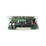
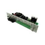
The internal layout of the 102618-01 features physical, jumper-programmable circuit paths that allow technicians to select transducer voltages, control power options, and data communication interfaces. The board relies on hardware links rather than software steps to assign operational voltage thresholds:
Voltages
Jumper Positions Required
12 VDC
W12 & W16, W1 & W6
24 VDC
W11 & W16, W1 & W5
48 VDC
W10 & W16, W1 & W4
110/125 VDC
W9 & W16, W1 & W3
110/120 VAC
W14 & W15, W2 & W8
220/240 VAC
W13 & W15, W2 & W7
Power-Up Inhibit and System Logic Integration
The card incorporates an automated Power-Up Inhibit function designed to stabilize industrial protection strings. Whenever the system experiences a power cycle or the main supply rail drops below functional operating levels, the card commands the rack’s monitoring modules to suppress their alert/danger alarms. Following power restoration, this internal inhibit sequence stays latched for approximately 2 seconds to let transient rotor dynamics settle.
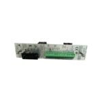
Furthermore, the rear power input module (PIM) interface accepts external mechanical contact closures. When triggered, this logic overrides active loops—placing monitors into manual bypass, zero-scaling analog recorder lines, disabling alarms, and de-energizing the main system OK safety relay to prevent false trips during scheduled loop tests.
Frequently Asked Questions
Q: Can the 102618-01 card be adjusted via software to change input voltage settings?
A: No. The card architecture relies entirely on physical plug-in jumpers (W1 through W16) located on the internal printed circuit board to select input supply parameters. Technicians must configure these jumpers manually before inserting the card.
Q: What is the main function of the front-panel or rear-terminal contact closure circuit?
A: The contact closure activates a global system bypass. It allows maintenance personnel to work on field transducers safely because it forces all associated monitors into a protected state where trip relays cannot accidentally shut down operating plant machinery.
Field Installation Guidelines
Static Dissipation Measures: Wear a standard grounded ESD wrist strap prior to handling the card to safeguard the delicate onboard jumper arrays and timing capacitors.
Jumper Verification Check: Confirm that the jumper layout matches local panel voltage requirements (such as 220 VAC vs 24 VDC layouts) before plugging the module into the system rack.
Terminal Screw Tension: Tighten the structural terminal screws located at the rear Power Input Module block to 0.56 N-m to prevent loose wire terminations from sparking.
Online Safety Verification: When inserting this card into a live machinery rack, ensure the system is switched to bypass to avoid triggering temporary ground-fault trip signals on adjacent eddy-current probe scaling loops.
Additional information
Weight
0.8 kg
Dimensions
320 × 80 × 60 mm
0.0
Average Rating
Rated
(0 Reviews)
Rated
0%
Rated
0%
Rated
0%
Rated
0%
Rated
0%
Be the first to review “Bently Nevada 102618-01 Power & Signal Input Card” Cancel reply


0.0 Average Rating Rated (0 Reviews)