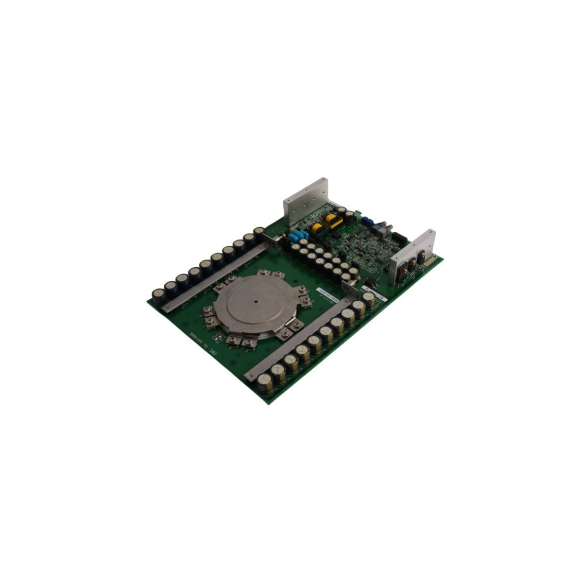
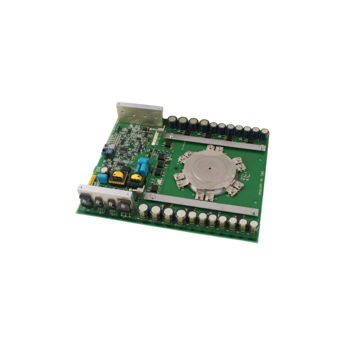
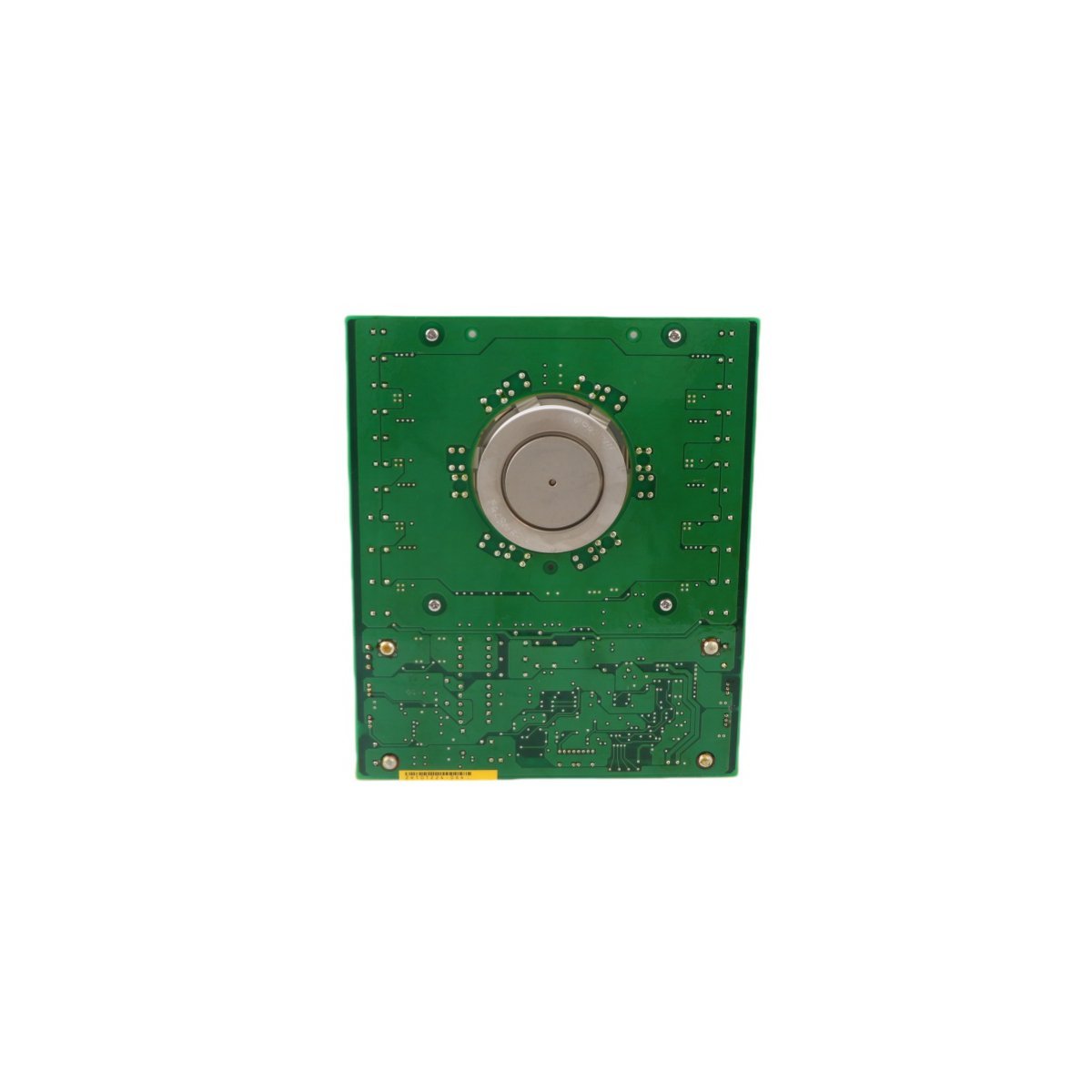
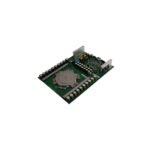
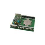
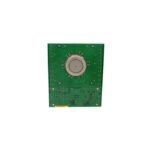
Configured for solid-state power switching and phase control in industrial drive systems, the Allen Bradley 80173-110-02-R (80173-110 Thyristor Board PCB) provides direct physical/electrical execution. It handles pulse triggering, gating signals, and high-current power distribution to maintain switching performance across control cabinets.
Hardware Specifications
Parameter
Specification
Model
80173-110-02-R
Brand
Allen Bradley
Origin
USA
Weight
1.56 kg
Dimensions
29.2 x 20.7 x 5.5 cm
Operating Temp
0 to 60 deg C
Power Consumption
Standard Backplane / Gate Drive Power
Current Rating
10 A Nominal Capacity
System
PLC / Industrial Drive System
HS Code
8537101190
Deterministic Network & Backplane Integration
The Allen Bradley 80173-110-02-R thyristor printed circuit board integrates directly into specialized power control assemblies and PLC-adjacent architectures. Backplane bus communication velocity and gate-firing synchronicity ensure deterministic switching execution without phase jitter. Solid-state switching dynamics prevent localized electrical noise from coupling into high-density Ethernet/IP or ControlNet networks. Correct firmware flash compatibility across drive interface modules maintains deterministic control over SCR gate trigger pulses during continuous operation.
Frequently Asked Questions
Q: What precautions should be taken regarding gate-trigger wiring and signal isolation?
A: Pulse transformer outputs and gate control traces must remain isolated from high-voltage AC mains. Shielded twisted-pair cables should be used for external control inputs to prevent parasitic capacitance and electromagnetic interference from causing false SCR firing.
Q: Can the board be swapped while power is applied to the main bus bar?
A: No. High-voltage AC/DC power must be completely disconnected and discharged before handling or replacing the thyristor board to prevent arc flash risks and silicon degradation.
Field Installation Guidelines
Enclosure Clearance & Thermal Dissipation: Mount the circuit board in a vertical orientation inside an IP54 or NEMA 12 rated enclosure. Maintain a minimum of 50 mm clearance above and below the assembly to allow passive convection across heat sinks and thyristor power modules.
Grounding & Shielding Integrity: Ensure the printed circuit board mounting standoffs establish low-impedance ground contact with the enclosure backplate. Drain wires from shielded control cables must terminate at a dedicated protective earth (PE) bus bar.
Terminal Torque Specifications: Secure high-current connections and wiring harness connectors using calibrated torque screwdrivers. Over-tightening can crack PCB traces near terminal blocks, while under-tightening leads to thermal hot spots under continuous 10 A load execution.
Additional information
Weight
1.56 kg
Country of Origin
USA
Dimension
29.2 x 20.7 x 5.5 cm
0.0
Average Rating
Rated
(0 Reviews)
Rated
0%
Rated
0%
Rated
0%
Rated
0%
Rated
0%
Be the first to review “Allen Bradley 80173-110-02-R Thyristor Board PCB” Cancel reply





0.0 Average Rating Rated (0 Reviews)