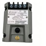
Configured for axial position monitoring in rotating machinery protection networks, the Bently Nevada 991-06-50-01-CN (991 Thrust Transmitter) provides direct physical/electrical execution.
Suffix Breakdown & Model Matrix
Option Code
Feature Type
Specification Selection
06
Full-Scale Range
0.6-0-0.6 mm (24-0-24 mils) linear range
50
System Length
5.0 meters (16.4 feet) proximity probe system
01
Mounting Option
35 mm DIN-rail clips included
CN
Agency Approval
ATEX/IECEx and Chinese NEPSI hazardous area marking
Hardware Specifications
Parameter
Specification
Model
991-06-50-01-CN
Brand
Bently Nevada
Origin
United States
Weight
0.28 kg
Dimensions
81.3 mm x 61.2 mm x 103.4 mm
Operating Temp
-35 to 85 deg C
Power Consumption
12 to 35 VDC input range (loop-powered)
Output Signal
4-20 mA proportional to shaft axial position
Loop Accuracy
Within +/- 1.5% over specified full-scale range
Current Limiting
23 mA maximum typical limit
Machinery Monitoring & TSI Characteristics
The transmitter processes raw high-frequency inputs from a non-contacting 3300 NSv proximity probe system and converts the target physical gap into a stable 4-20 mA loop current. During this conversion, the internal electronics perform real-time gap voltage validation (-10 VDC nominal targets) to establish precise shaft position baselines. Furthermore, the embedded circuitry incorporates signal cross-talk suppression to isolate the sensitive transducer loop from adjacent channel interference. Because the transmitter shares a direct linear relationship with the specific eddy-current probe scaling, it smoothly translates minute micro-inch deviations into proportional industrial signals. Consequently, this continuous output allows connected plant control architectures to evaluate rotor dynamics and immediately execute protective machinery trips when axial displacement parameters cross safe thresholds.
Frequently Asked Questions
Q: How does the transmitter handle sensor failures or loose extension cable connections?
A: The hardware includes an integrated Not OK/Signal Defeat circuit that forces the current loop output below 3.6 mA within 100 microseconds of a detected fault, which prevents false alarms at the control system.
Q: Can test equipment capture dynamic diagnostic signals directly from this module?
A: Yes, the unit features an integrated coaxial PROX OUT connector that provides an unisolated dynamic voltage signal for external oscilloscopes or data analyzers without interrupting the primary 4-20 mA loop.
Q: What function does the internal power-up inhibit circuit serve?
A: The power-up inhibit circuit suppresses the output signal during initial power application, which actively eliminates data transmission errors caused by line voltage transients.
Field Installation Guidelines
Snap the transmitter housing firmly onto a standard 35 mm DIN rail using the integrated mounting clips, or ensure rigid structural attachment when utilizing alternative bulkhead screw configurations.
Connect the 3300 NSv coaxial extension cable to the dedicated transmitter terminal base, then torque the connection to the recommended specification to prevent signal attenuation.
Route all loop wiring inside grounded metal conduits away from high-voltage AC electric motor cables, because this practice actively blocks electromagnetic noise injection.
Calibrate the loop output using the non-interacting external zero and span potentiometers located underneath the front label to match specific mechanical displacement baselines.
0.0
Average Rating
Rated
(0 Reviews)
Rated
0%
Rated
0%
Rated
0%
Rated
0%
Rated
0%
Be the first to review “Bently Nevada 991-06-50-01-CN Thrust Transmitter Module” Cancel reply


0.0 Average Rating Rated (0 Reviews)