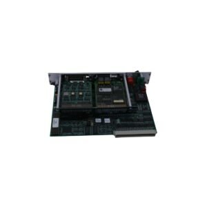
The Bently Nevada 3300/50-02-02-00-00, also cataloged as the 3300/50 Tachometer Monitor, operates as a dedicated hardware component within the legacy 3300 Monitoring System framework. This rack-mounted module continuously processes data to deliver precise shaft rotative speed, zero speed, and rotor acceleration diagnostics for critical industrial machinery.
Suffix Breakdown & Model Matrix
3300/50: Core product identifier for the Tachometer Monitor Module.
02: Rpm Range option configuring the internal logic for a standard speed range profile.
02: Transducer Input option configured for direct compatibility with standard proximity probe and Proximitor sensor networks.
00: Agency Approval option designating a standard industrial base build without specialized regional variants.
Proportional 4-20 mA or 0-10 VDC recorder telemetry
Rotor Dynamics and Signal Conditioning
Consequently, the 3300/50-02-02-00-00 hardware executes high-speed event-period processing to translate multi-tooth or single-keyway pulse events into direct angular velocity data. During machine startup sequences, the module monitors incoming waveforms to execute accurate gap voltage validation, tracking the underlying DC offset against nominal -10 VDC targets to ensure clean tooth-passing pulse separation. Meanwhile, the input isolation circuitry maintains strict cross-talk suppression against adjacent radial or axial channels sharing the same backplane. This electrical separation blocks transient electromagnetic spikes from distorting speed readings, enabling fast calculation of rotor dynamics phase angles and machine trip logic.
Frequently Asked Questions
Q: Why does a tachometer monitor require accurate gap voltage tracking if it only counts speed pulses?
A: Because the proximity sensor must clearly distinguish the physical transition of a keyway or gear tooth, the module tracks the DC gap voltage to ensure the probe remains centered within its linear calibration zone. Consequently, improper gap tracking leads to missed pulses or false double-triggering during rotation.
Q: How does the monitor respond if the input speed sensor signal drops completely during high-speed machine operation?
A: When the pulse frequency falls below threshold limits or a wire breaks, the internal Not OK logic instantly illuminates the front-panel Not OK indicator. Subsequently, the module bypasses current speed outputs and locks associated trip relays to prevent a false underspeed trip.
Field Installation Guidelines
Module Insertion: First, align the circuit board side edges with the plastic tracks of the targeted 3300 rack slot. Next, slide the module firmly into the passive backplane until the rear connectors mate completely. Finally, tighten the front faceplate retention hardware to secure the chassis ground.
Transducer Shielding: Terminate the incoming sensor coaxial shield explicitly at the designated rear terminal block ground strip. Conversely, never ground the shield layer at the machine casing or intermediate junction boxes, as single-point grounding stops external ground loops from corrupting pulse data.
Wiring Separation: Route low-voltage pulse-input wiring through separate, dedicated conduits. Furthermore, isolate these speed signal lines from heavy-current three-phase AC distribution leads and variable frequency drive cables to suppress external inductive noise coupling.
Additional information
Weight
0.6 kg
Dimensions
26 × 20 × 12 mm
0.0
Average Rating
Rated
(0 Reviews)
Rated
0%
Rated
0%
Rated
0%
Rated
0%
Rated
0%
Be the first to review “Bently Nevada 3300/50-02-02-00-00 Tachometer Monitor” Cancel reply


0.0 Average Rating Rated (0 Reviews)