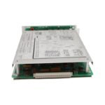
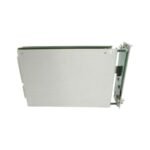
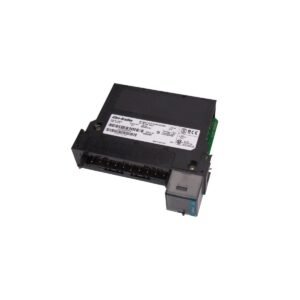
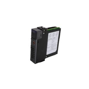
The 3300/20-12-01 is a genuine dual thrust position monitor manufactured by Bently Nevada. This industrial component is available as Brand New, Original Stock with Global Shipping options for integration into turbine supervisory instrumentation racks.
The Bently Nevada 3300/20-12-01, also cataloged as the 3300/20 Dual Thrust Position Monitor, operates as a dedicated hardware component for axial shaft position measurement within 3300 Monitoring System platforms. Specifically, this module accepts raw input signals from two independent proximity transducer systems. It actively processes the direct current (DC) voltage changes that occur as a rotating shaft moves toward or away from the probe tips. Consequently, this hardware executes continuous protection by driving internal alarm relays, while simultaneously delivering independent analog recorder outputs proportional to the physical axial displacement of the machinery rotor.
Hardware Specifications
Parameter
Specification
Model
3300/20-12-01
Brand
Bently Nevada
Origin
USA
Weight
0.95 kg
Dimensions
241 mm x 24.4 mm x 103 mm
Operating Temp
0 to 65 deg C
Power Consumption
7.2 W typical
Signal Inputs
Two independent proximity probe inputs (axial displacement)
System Accuracy
Within 0.5 percent of full scale range
Analog Outputs
Dual 4-20 mA or 1-5 VDC recorder outputs per channel
Machinery Monitoring and TSI Characteristics
To ensure accurate displacement metrics, the Bently Nevada 3300/20-12-01 incorporates high-speed analog logic for eddy-current probe scaling. This circuitry actively converts physical rotor displacement into precise electrical values based on the nominal linear range of the sensors. During initial machinery alignment, field technicians execute gap voltage validation procedures to establish a steady -10 VDC baseline, which centers the probe within its calibrated measurement zone. Because axial shifts directly impact thrust bearing oil film thickness, the module utilizes rapid cross-talk suppression and input signal isolation. As a result, these filters actively prevent high-frequency voltage fluctuations from corrupting the static position metrics.
Frequently Asked Questions
Q: How does the module handle a single sensor failure in a redundant thrust configuration?
A: The monitor incorporates a NOT OK circuit that continuously tracks the input gap voltage. If one sensor drops outside the linear threshold, the circuit immediately activates the specific NOT OK LED, and the channel automatically bypasses alarm execution to prevent false machine shutdowns.
Q: Can field personnel hot-swap the 3300/20 module under live system power?
A: Yes. The rear card edge connectors permit safe insertion and removal while the 3300 rack chassis remains energized. Therefore, technicians can replace the module without powering down the entire machinery protection system.
Q: What does the “12” suffix code designate in this specific model configuration?
A: The “12” suffix designates the specific option combination chosen for the scale range and the transducer type. Thus, this code matches the module’s internal calibration to standard 8 mm or 11 mm Proximitor systems with designated millimeter or mil scaling.
Field Installation Guidelines
Chassis Engagement: First, align the module circuit board with the upper and lower chassis card guides inside the 3300 rack slot. Next, push firmly inward until the rear pins seat completely into the backplane socket, and then torque the front panel captive screws finger-tight.
Shield Grounding Terminal: Terminate the shield drain wires of the transducer extension cables strictly at the rear terminal block chassis ground. Avoid grounding the shield at the sensor housing end, because this dual termination introduces ground loops that distort DC voltage stability.
Proximitor Field Wiring: Ensure all field wiring between the Proximitor sensor and the rear input terminal block uses dedicated shielded twisted-pair cabling. Furthermore, maintain a minimum separation distance of 150 mm from high-current AC power distribution cables to minimize noise injection.
Terminal Integrity: Finally, check that all terminal block pressure screws maintain a torque rating of 0.56 N-m. This consistent torque secures the connection points and prevents environmental oxidation of the conductors over time.
Additional information
Weight
0.95 kg
Dimensions
70 × 120 × 60 mm
0.0
Average Rating
Rated
(0 Reviews)
Rated
0%
Rated
0%
Rated
0%
Rated
0%
Rated
0%
Be the first to review “Bently Nevada 3300/20-12-01 Dual Thrust Position Monitor Module” Cancel reply


0.0 Average Rating Rated (0 Reviews)