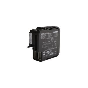
Configured for continuous machinery vibration protection on medium-speed machinery, the Bently Nevada 3300/15-03-01-01-00-00-00 (3300/15 Dual Velocity Monitor) provides direct physical/electrical execution. This two-channel rack-mounted module accepts analog input signals from electro-magnetic velocity transducers. Consequently, the internal microprocessors convert these raw absolute vibration inputs into engineering units, continuously writing dynamic measurement data across the 3300 chassis backplane motherboard.
Suffix Breakdown & Model Matrix
3300/15: Core module identifier for the Dual Velocity Monitor series.
01: Transducer type input option calibrated for standard Bently Nevada Seismoprobe velocity sensors.
01: Agency approval option certifying the assembly for CSA Division 2 / ATEX Zone 2 environments.
00: Internal alarm relay configuration option specifying that the monitor contains no individual mechanical relay boards.
00: Trip Multiply option selection designating standard factory bypass and magnification coefficients.
00: Front panel display option equipping the module with a standard LED alert array without an LCD screen.
Hardware Specifications
Parameter
Specification
Model
3300/15-03-01-01-00-00-00
Brand
Bently Nevada
Origin
United States
Weight
1.01 kg
Dimensions
192 mm x 140 mm x 89 mm
Operating Temp
0 deg C to +65 deg C
Power Consumption
2.1 W nominal electrical demand
Input Impedance
10 kOhm on transducer channels
Channel Density
2 independent velocity input channels
Signal Filtering
Standard 10 Hz to 1000 Hz bandpass filter
Accuracy
Within +/- 0.5% of full-scale value typical
Dynamic Output
Raw unbuffered voltage signal via front panel coaxial BNC jacks
Eddy-Current Probe Scaling and Rotor Dynamics
Although the 3300/15-03-01-01-00-00-00 interfaces primarily with seismic moving-coil transducers, the instrument rack framework links this module to adjacent eddy-current probe loops via the common power bus. During multi-module verification checkouts, technicians assess the overall rack layout, checking gap voltage validation lines on neighboring displacement channels to preserve the standard 7.87 V/mm (200 mV/mil) sensor response curve. Furthermore, the specialized internal filter networks provide substantial cross-talk suppression between the velocity sensor lines and the high-frequency RF lines of adjacent proximity monitors. This design configuration maintains signal purity when tracking complex rotor dynamics on fluid-film bearings. As a result, micro-structural variances in casing vibration transmit accurately to the backplane motherboard, preventing stray electromagnetic fields from generating parasitic voltage deviations in the vibration logs.
Frequently Asked Questions
Q: How does the velocity monitor signal logic respond if a field transducer wire disconnects or breaks?
A: The monitor incorporates an integrated Not OK hardware tracking circuit. If an open-circuit or short-circuit fault occurs on either velocity sensor line, the internal system isolates that channel within 100 milliseconds and blocks false Alert or Danger relay trips.
Q: Can an instrument technician adjust the analog recorder output formatting directly in the field?
A: Yes, the recorder outputs are field-programmable. The technician changes internal hardware jump links on the circuit board to toggle the independent channel outputs among 4-20 mA, 0 to -10 VDC, or +1 to +5 VDC configurations.
Field Installation Guidelines
Chassis Slot Seating Steps: Slide the monitor module smoothly into the designated card guide rails of the 3300 rack chassis. Push the front panel inward firmly until the rear multi-pin edge connector seats completely into the backplane motherboard socket, then torque the panel retaining screws.
Field Wiring and Shield Isolation: Route the transducer connections to the rear terminal blocks using twisted-pair shielded instrumentation wire. Connect the outer shield drain wire to the specific chassis earth terminal on the rack backplane, and leave the shield floating at the sensor housing to prevent parasitic ground loops.
BNC Diagnostic Interface Safety: Use the front panel ungrounded BNC jacks to collect raw structural vibration waves for external spectrum analyzers. Technicians must connect diagnostic equipment with a minimum input impedance of 100 kOhm to avoid altering the active measurement signal path.
Additional information
Weight
1 kg
Dimensions
26 × 36 × 20 mm
0.0
Average Rating
Rated
(0 Reviews)
Rated
0%
Rated
0%
Rated
0%
Rated
0%
Rated
0%
Be the first to review “Bently Nevada 3300/15-03-01-01-00-00-00 3300/15 Dual Velocity Monitor” Cancel reply


0.0 Average Rating Rated (0 Reviews)