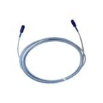
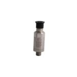
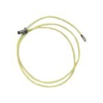
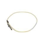
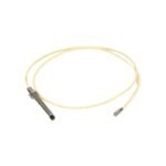
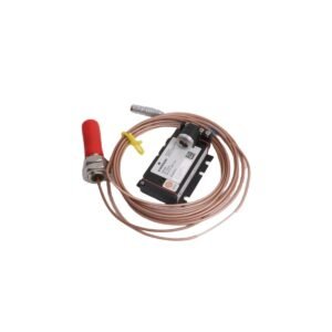
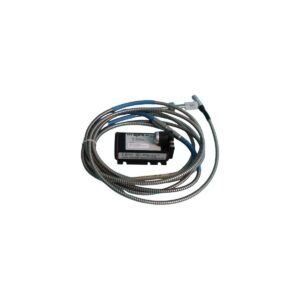
Configured for machinery condition monitoring in vibration protection networks, the Bently Nevada 21500-00-12-10-02 (Bently Nevada 21500 Proximity Probe Assembly) provides direct physical/electrical execution. Specifically, this non-contacting sensor measures static and dynamic displacement of a rotating shaft relative to the probe tip. Consequently, the hardware generates a precise analog output signal that maps directly to the physical movement of the observed component, allowing real-time tracking of critical mechanical parameters.
Hardware Specifications
Parameter
Specification
Model
21500-00-12-10-02
Brand
Bently Nevada
Origin
United States
Weight
0.28 kg
Dimensions
Threaded case with integral coaxial lead
Operating Temp
-35 to +177 deg C
Power Consumption
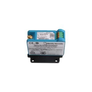
Passive element, external driver powered
Measurement Type
Proximity / Displacement
Thread Size
Standard physical mounting thread
Eddy-Current Probe Scaling and Gap Voltage Validation
Because the sensor tip relies on electromagnetic fields, changes in material properties alter eddy-current probe scaling accuracy. Technicians must perform strict gap voltage validation during physical installation, adjusting the mechanical position until the sensor output registers the target -10 VDC baseline. Furthermore, routing the sensor lead requires robust cross-talk suppression via dedicated conduit pathways. This practice actively blocks external electromagnetic interference, which prevents distortion of the high-frequency carrier wave and ensures clean reporting of rotor dynamics.
Frequently Asked Questions
Q: How does proper mechanical mounting support cross-talk suppression in this assembly?
A: Enforcing the required physical clearance between adjacent probe tips limits electromagnetic field overlap. Therefore, precise spacing prevents mutual induction and blocks cross-talk.
Q: What step must precede gap voltage validation during field calibration?
A: Technicians must firmly lock the probe case threads into the housing structure. Securing the physical position ensures that subsequent -10 VDC target measurements remain stable during operation.
Field Installation Guidelines
Thread the probe assembly carefully into the mounting bracket to avoid stripping the physical adjustment threads.
Route the integral coaxial cable with a minimum bend radius of 25 mm to prevent inner core fracturing or impedance shifts.
Wipe the probe tip completely clean of oil, grease, or metallic debris prior to final position locking.
Conclude the physical installation by verifying that the outer coaxial connector body remains isolated from structural machine ground.
Additional information
Weight
0.60 kg
Dimensions
50 × 60 × 70 mm
0.0
Average Rating
Rated
(0 Reviews)
Rated
0%
Rated
0%
Rated
0%
Rated
0%
Rated
0%
Be the first to review “Bently Nevada 21500-00-12-10-02 Proximity Probe Assembly” Cancel reply


0.0 Average Rating Rated (0 Reviews)