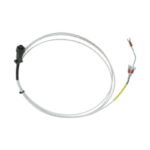
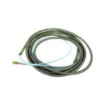
The Bently Nevada 1X35668, also cataloged as the 1X35668 Extension Cable, operates as a dedicated hardware component for remote mechanical vibration monitoring within 3300 XL NSv Proximity Transducer System platforms.
The Bently Nevada 1X35668 preserves the exact electrical length required for precise eddy-current probe scaling, matching the calibration impedance of the paired 3300 NSv transducer. During field setup, this extension cable bridges physical distances to deliver unattenuated raw signals, allowing accurate gap voltage validation (-10 VDC targets) at the Proximitor sensor terminals. By shielding low-voltage high-frequency signals, the cable structure minimizes attenuation across critical frequencies, supporting accurate evaluation of rapid rotor dynamics and preventing phase distortion. Additionally, integrated coaxial insulation design optimizes cross-talk suppression when multiple probe runs route through shared machine housing channels.
Frequently Asked Questions
Q: Does trimming the physical length of the 1X35668 cable affect system accuracy?
A: Yes, proximity transducer systems rely on precise electrical length and capacitance; cutting or altering the cable changes its tuning and invalidates the system calibration.
Q: How should field technicians verify structural connection integrity across the extension links?
A: Technicians use a multimeter to check loop resistance and confirm that the gap voltage validation matches the expected -10 VDC baseline values under static conditions.
Field Installation Guidelines
Connector Thread Engagement: Finger-tighten the coaxial connectors, then apply the industry-standard minimum torque using a specialized connector wrench to prevent loose contact or thread stripping.
Insulation Sleeving: Install clear silicone or heat-shrink terminal insulation boots over the mated coaxial connections to isolate the shield from touching structural machine framework.
Bend Radius Protection: Maintain a minimum physical bend radius of 25.4 mm throughout the cable routing to eliminate inner conductor stress and prevent signal degradation.
Additional information
Weight
1 kg
Dimensions
26 × 16 × 20 mm
0.0
Average Rating
Rated
(0 Reviews)
Rated
0%
Rated
0%
Rated
0%
Rated
0%
Rated
0%
Be the first to review “Bently Nevada 1X35668 3300 XL NSv Proximity Transducer System Extension Cable” Cancel reply


0.0 Average Rating Rated (0 Reviews)