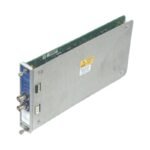
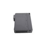
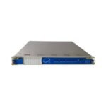
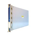
Configured for high-density alarm orchestration and voting logic execution in the 3500 Machinery Protection System, the Bently Nevada 149986-01 (149986-01 16-Channel Relay Control Module) provides direct physical/electrical execution. This full-height front processor card processes alert and danger statuses derived from input monitors across the rack backplane. Consequently, by compiling complex AND/OR drive statements, the device initiates precise automated safety trip behaviors or links machine status registers directly to external safety systems.
Hardware Specifications
Parameter
Specification
Model
149986-01
Brand
Bently Nevada
Origin
United States
Weight
0.70 kg
Dimensions
241.0 mm x 24.4 mm x 242.0 mm
Operating Temp
-30 to +65 deg C
Power Consumption
10.0 W maximum
Switching Channels
16 programmable channels
Voting Logic Support
Complete AND / OR matrix formulation via configuration software
System Placement
Full-height front slot (any slot right of the TDI module)
Software Prerequisite
3500 Rack Configuration Software version 3.3 or higher
Rotor Dynamics and Cross-Talk Suppression Engineering
The Bently Nevada 149986-01 serves as the central logic aggregator that translates dynamic rotor dynamics parameters into protective physical hardware actions. Specifically, the card continuously scans backplane data buses, employing localized digital cross-talk suppression to handle rapid multi-channel status state shifts simultaneously. Internal processing chips track real-time transducer conditions, enforcing gap voltage validation loops before committing a trip state. If an eddy-current probe drifts away from standard -10 VDC targets, the module identifies the “Not OK” status condition immediately. This response prevents sensor defects from corrupting the calibrated eddy-current probe scaling calculations, avoiding unintended machinery trip interlock activation.
Frequently Asked Questions
Q: Can an engineer swap out the 149986-01 module while the remaining slots in the 3500 rack stay powered?
A: Yes, technicians can perform hot-swap replacement on the front-facing 149986-01 processor module while the rack is energized. However, removing the card instantly inactivates all 16 associated alarm outputs; therefore, operators must bypass external trip loops manually beforehand to prevent emergency machinery shutdown.
Q: How do technicians configure the individual channel states for normally energized versus normally de-energized operation?
A: Technicians adjust the relay operation states using hardware switches located directly on the module circuit board. Specifically, these switches control groups of four channels at a time, allowing engineers to match the physical output behavior with plant fail-safe design parameters.
Field Installation Guidelines
Insert the full-height 149986-01 card into its chosen front chassis slot, taking care to line up the plastic guide rails before pushing the card into the backplane connectors.
Secure the module by tightening the upper and lower faceplate screws to a maximum torque setting of 0.6 N m to maintain proper chassis grounding.
Verify that the matching rear I/O module resides in the exact slot matching the front 149986-01 processor card location to ensure correct channel signal alignment.
Run all low-voltage logic signal circuits away from close proximity to heavy AC distribution pathways to eliminate external electromagnetic interference patterns from the rack interface.
Additional information
Weight
0.6 kg
Dimensions
20 × 20 × 12 mm
0.0
Average Rating
Rated
(0 Reviews)
Rated
0%
Rated
0%
Rated
0%
Rated
0%
Rated
0%
Be the first to review “Bently Nevada 149986-01 3500/33 16-Channel Relay Control Module” Cancel reply


0.0 Average Rating Rated (0 Reviews)