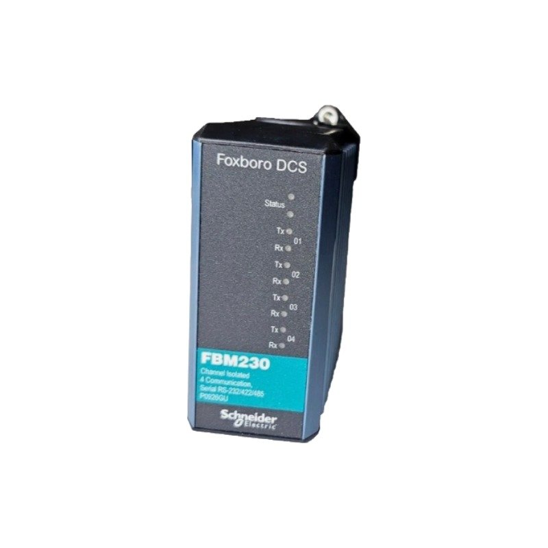
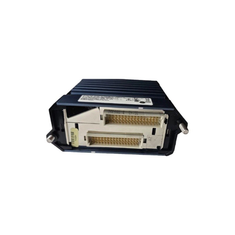
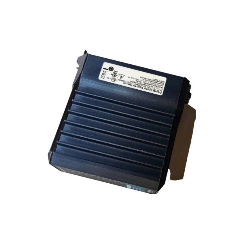
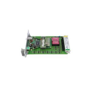
The Foxboro FBM230, also cataloged as the FBM230 Field Device System Interface Module, operates as a dedicated hardware component for serial communication interface processing within Foxboro I/A Series DCS networks. The module integrates four independent serial channels that can be individually configured via software to interface with field devices utilizing standard EIA communication protocols.
Hardware Specifications
Parameter
Specification
Model
FBM230
Brand
Foxboro
Origin
USA
Weight
0.28 kg
Dimensions
114 mm x 45 mm x 105 mm
Operating Temp
-20 to +70 deg C
Power Consumption
3.5 W maximum
Channel Capacity
4 software-configurable ports
Serial Interfaces
RS-232, RS-422, RS-485
Channel Isolation
Galvanic isolation per channel and to backplane
Network Topologies
Direct point-to-point (RS-232/422), Multidrop (RS-485), Modem connection
Field Device Interface and Channel Isolation
Each of the four communication channels on the module supports independent software configuration for RS-232, RS-422, or RS-485 physical layer standards. Channel-to-channel isolation prevents ground loop interference across multidrop lines and isolated field transmitters. The system architecture supports direct field device connection, modem integration over RS-232, and multidrop bus configurations via RS-485, with options for inline intrinsic safety barrier connection at the termination assembly interface.
Frequently Asked Questions
Q: Can different ports on the same module operate on different physical communication standards simultaneously?
A: Yes, each of the four ports is software-configurable independently, allowing simultaneous operation of RS-232, RS-422, and RS-485 protocols across different ports on a single module.
Q: How is signal line isolation maintained when interfacing with intrinsic safety barriers?
A: Intrinsic safety barriers are connected between the field termination assembly (TA) and field devices, maintaining galvanic separation between field circuits and system backplane logic.
Field Installation Guidelines
Mount the field termination assembly (TA) on the DIN rail prior to module insertion into the baseplate position.
Confirm that termination assembly jumpers or wiring configurations correspond to the selected RS-232, RS-422, or RS-485 physical interface requirements.
Align module connector pins with baseplate guide slots and seat the module securely until side latches click.
Route serial communication cables away from high-voltage field wiring and power conductors to minimize electro-magnetic interference.
Connect cable shielding to the ground bus at a single point on the termination assembly according to system grounding standards.
Additional information
Weight
0.28 kg
Dimensions
64 × 41 × 32 mm
0.0
Average Rating
Rated
(0 Reviews)
Rated
0%
Rated
0%
Rated
0%
Rated
0%
Rated
0%
Be the first to review “Foxboro FBM230 Field Device System Interface Module” Cancel reply













0.0 Average Rating Rated (0 Reviews)