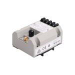
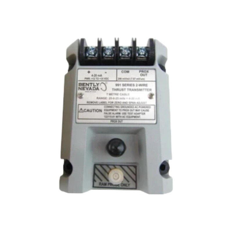
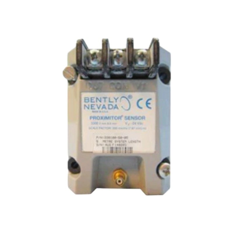
The Bently Nevada 990-05-50-02-00, also cataloged as the 990 Proximity Transmitter, operates as a dedicated hardware component for non-contacting vibration and displacement measurements within machine monitoring networks. Specifically, the transmitter conditions high-frequency radio frequency (RF) signals from an eddy-current probe system and subsequently converts the physical gap into a linear 4-20 mA DC current loop. Consequently, this design executes the direct integration of machinery parameters into distributed control systems (DCS) or programmable logic controllers (PLC) without an intermediate monitor rack.
Hardware Specifications
Parameter
Specification
Model
990-05-50-02-00
Brand
Bently Nevada
Origin
USA
Weight
0.25 kg (0.55 lbs)
Dimensions
81.3 mm x 61.2 mm x 50.8 mm
Operating Temp
-35 deg C to +85 deg C
Power Consumption
Less than 1.0 W nominal
Input Signal
Compatible Proximity Probe and Extension Cable
Output Signal
4-20 mA DC (Linear displacement scaled)
System Supply Voltage
12 to 35 VDC at the transmitter terminal
Mounting
35 mm DIN-rail or panel mount options
Eddy-Current Probe Scaling and Transducer Dynamics
The Bently Nevada 990-05-50-02-00 utilizes precise eddy-current probe scaling to capture rapid target movements and analyze rotor dynamics. During commissioning, engineers perform gap voltage validation (-10 VDC targets) within the calibrated linear range, thereby verifying proper sensor positioning relative to the observed shaft. Furthermore, the internal electronics deploy integrated cross-talk suppression circuitry; as a result, the hardware minimizes electrical interference even when multiple sensor lines run through parallel wire conduits.
Frequently Asked Questions
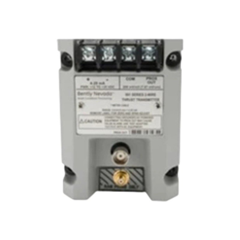
Q: Why does the transmitter include a continuous BNC connector on the housing?
A: The BNC connector provides a dynamic voltage output proportional to the unfiltered sensor signal. Therefore, technicians can connect vibration analyzers and data collectors directly for diagnostics without interrupting the primary 4-20 mA control loop.
Q: How does the module handle hazardous area environments?
A: The transmitter supports hazardous area deployment. However, technicians must install the module in combination with certified intrinsic safety barriers or galvanic isolators that match the electrical parameters specified in the Bently Nevada approval documentation.
Field Installation Guidelines
Shielding and Grounding: First, terminate the coaxial extension cable shield directly at the designated transmitter terminal. Afterwards, ground the field-side 4-20 mA instrumentation cable shield at a single point, typically at the control room I/O cabinet ground bus, to prevent ground loop noise.
Conduit and Routing Rules: Always route probe cables and transmitter output loops inside dedicated, grounded metal conduits. In addition, avoid running signal wiring in the same tray or conduit as high-voltage power distribution lines or variable speed drive (VFD) motor cables.
Mechanical Mounting: Install the transmitter housing on a standard 35 mm DIN rail or, alternatively, bolt it directly to a flat panel inside a protected enclosure. If installing in outdoor or corrosive process environments, select an enclosure rating of IP54 or higher.
Additional information
Weight
0.25 kg
Dimensions
65 × 70 × 85 mm
0.0
Average Rating
Rated
(0 Reviews)
Rated
0%
Rated
0%
Rated
0%
Rated
0%
Rated
0%
Be the first to review “Bently Nevada 990-05-50-02-00 Proximity Transmitter” Cancel reply











0.0 Average Rating Rated (0 Reviews)