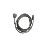
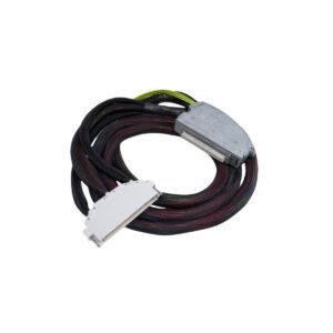
The Bently Nevada 79748-01, also cataloged as the 79748-01 Extension Cable, operates as a dedicated hardware component for RF signal transmission within Bently Nevada 3300 5mm and 8mm Proximity Transducer Systems.
Hardware Specifications
Parameter
Specification
Model
79748-01
Brand
Bently Nevada
Origin
United States
Weight
0.15 kg
Dimensions
3.0 m length
Operating Temp
-51 deg C to +177 deg C
Power Consumption
Passive component (0 W)
System Compatibility
3300 5mm and 8mm systems
Cable Impedance
50 Ohm nominal
Eddy-Current Probe Scaling and System Calibration
The Bently Nevada 79748-01 ensures system integrity during eddy-current probe scaling by maintaining a constant electrical length matching the requirements of the proximity sensor oscillator/demodulator circuit. When verifying the gap voltage validation (-10 VDC targets), technicians must utilize the exact combined length of the probe lead and extension cable to prevent calibration drift. Mismatched cable lengths alter the overall impedance, which directly compromises the accurate observation of rotor dynamics and introduces signal errors. Furthermore, the specialized coaxial construction incorporates internal shielding geometries engineered for cross-talk suppression, preventing adjacent high-frequency phase and vibration signals from corrupting the industrial machinery monitor backplane inputs.
Frequently Asked Questions
Q: Does the 79748-01 extension cable support hot-swapping while the machinery monitoring system is online?
A: No. Disconnecting or connecting the extension cable while the proximity sensor driver is energized disrupts the RF loop, inducing an immediate voltage fault state on the associated monitor card. Technicians must bypass the machine trip relays prior to servicing the cable assembly.
Q: How does a deviation in the total specified cable length affect the proximity transducer system output?
A: Proximity systems rely on a fixed resonant circuit frequency calibrated to a specific electrical length. Deviating from the required total length alters the scale factor from the standard 200 mV/mil (7.87 V/mm), leading to inaccurate gap voltage measurements and incorrect vibration readings.
Field Installation Guidelines
Minimum Bend Radius Constraints: Maintain a minimum bend radius of 25.4 mm (1.0 inch) during routing to prevent structural damage to the internal coaxial dielectric layers and the outer protective jacket.
Terminal Connector Torque: Hand-tighten the miniature coaxial connectors (coaxial male/female links) until they sit firmly, then apply a one-quarter turn with specialized connector wrenches. Do not use standard pliers, as over-tightening deforms the contact pins.
Shielding and Insulation Isolation: Install the connection point inside a dedicated environmental conduit junction box (terminal boot). Ensure the outer metal braid does not ground against intermediate structural steel or cable trays, preventing structural ground loop interference.
Additional information
Weight
0.15 kg
Dimensions
60 × 26 × 40 mm
0.0
Average Rating
Rated
(0 Reviews)
Rated
0%
Rated
0%
Rated
0%
Rated
0%
Rated
0%
Be the first to review “Bently Nevada 79748-01 Proximity Transducer System Extension Cable” Cancel reply


0.0 Average Rating Rated (0 Reviews)