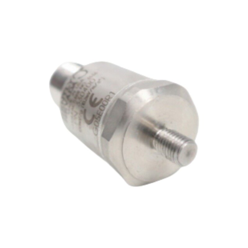
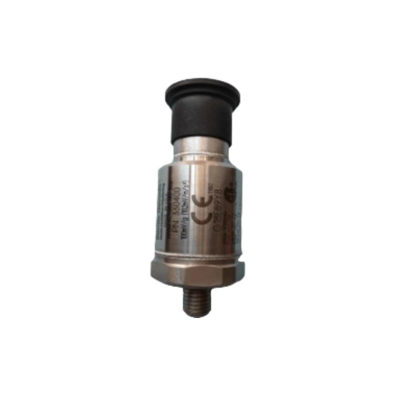
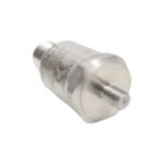
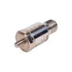
Configured for casing acceleration measurements in machinery protection platforms, the Bently Nevada 330400-01-00 (330400 Accelerometer Transducer) provides direct physical/electrical execution. The hardware targets high-frequency vibration profiles such as gear mesh signatures and operates under the compliance mandates of the American Petroleum Institute Standard 670. It executes mechanical-to-electrical transduction via a piezoelectric shear-mode element, outputting a continuous voltage signal to upstream monitoring monitors across internal processing systems.
Suffix Breakdown & Model Matrix
Parameter
Configuration Type
Technical Specification
330400
Base Model
Standard accelerometer transducer, 50 g peak amplitude limit, 100 mV/g sensitivity
-01
Mounting Thread Option
1/4-28 UNF integral male mounting stud
-00
Agency Approval Option
No Approvals (Standard uncertified configuration for non-hazardous zones)
Hardware Specifications
Parameter
Specification
Model
330400-01-00
Brand
Bently Nevada
Origin
United States
Weight
99 g typical (excluding interconnecting cable assembly)
Dimensions
23 mm diameter, 59 mm total height including mounting stud
Operating Temp
-55 deg C to +121 deg C
Power Consumption
2 mA bias current nominal, driven by external -24 VDC supply voltage
Sensitivity
10.2 mV/m/s2 (100 mV/g) plus/minus 5% at 100 Hz frequency
Acceleration Range
490 m/s2 (50 g) peak overall acceleration limit
Frequency Response
10 Hz to 15 kHz (600 cpm to 900,000 cpm) plus/minus 3 dB
Amplitude Linearity
plus/minus 1% across the full scale acceleration range up to 490 m/s2
Mounted Resonant Frequency
Greater than 30 kHz minimum threshold
Output Bias Voltage
-8.5 VDC plus/minus 0.5 VDC nominal referenced to COM
Case Material
316L stainless steel, hermetically sealed construction
Connector Interface
3-pin MIL-C-5015 top-exit electrical receptacle
Enclosure IP Rating
Equivalent to IP 68 protection class (dust tight and continuous immersion)
Machinery Monitoring & Rotor Dynamics Integration
The sensor interfaces directly with multi-channel monitoring blocks to map high-frequency structural elements alongside proximity measurement systems. While eddy-current probe scaling maps low-frequency shaft motion and verifies gap voltage validation (-10 VDC targets), this casing acceleration component captures higher harmonic vibrations. The data correlates with multi-axis casing displacement matrices to assess absolute rotor dynamics under high-velocity transients. Internal structural filtering maintains signal isolation, providing cross-talk suppression between adjacent orthogonal acceleration axes within high-density sensor arrays.
Frequently Asked Questions
Q: What is the maximum acceptable field cable length for the 330400-01-00 without signal degradation?
A: The transducer supports a maximum operational cable distance of 305 meters (1000 feet) when terminated with approved high-impedance, 3-conductor shielded instrumentation cable, without altering the calibrated scale factor.
Q: Does this hardware configuration allow hot-swap connection to an active monitor channel?
A: The hardware itself does not contain current-limiting safety switches for live connection. Disconnect the input power from the 3500/42M or equivalent rack monitor card before mating or unmating the 3-pin MIL-C-5015 electrical connector to prevent voltage transients on the signal line.
Q: How does the base strain sensitivity affect low-frequency performance?
A: The hardware exhibits a base strain sensitivity of 0.005 g/microstrain. Thermal or mechanical flexion of the mounting base can induce low-frequency voltage shifts, which must be attenuated by enforcing the specified mounting surface flatness and torque parameters.
Field Installation Guidelines
Physical installation requires a perpendicular mating surface machined to a smoothness profile of 32 microinch rms or superior. Drill and tap the casing target to accept the integrated 1/4-28 UNF male stud, verifying that the hole depth allows full thread engagement without bottoming out the sensor body. Apply a uniform tightening torque of precisely 4.1 N m (3.0 ft lb); under-torqueing degrades high-frequency transmission efficiency, while over-torqueing introduces permanent case strain that biases the internal piezoelectric element.
Electrical shielding continuity must be maintained from the 3-pin MIL-C-5015 receptacle to the diagnostic terminal blocks. Terminate the outer copper braid shield exclusively at the monitoring rack instrumentation ground bus. The sensor casing is internally isolated from the processing circuitry, preventing ground loop circulation paths. Route all field wiring through dedicated, grounded metal conduit away from heavy current lines, structural switchgear, or variable frequency drive cables to suppress external electromagnetic interference.
Additional information
Weight
0.99 kg
Dimensions
65 × 70 × 80 mm
0.0
Average Rating
Rated
(0 Reviews)
Rated
0%
Rated
0%
Rated
0%
Rated
0%
Rated
0%
Be the first to review “Bently Nevada 330400-01-00 Accelerometer Transducer” Cancel reply











0.0 Average Rating Rated (0 Reviews)