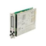
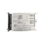
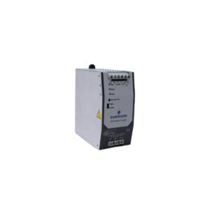
The Bently Nevada 3300/16-11-01-02-00-02-00, also cataloged as the 3300/16 XY Vibration Monitor, operates as a dedicated hardware component for continuous radial vibration monitoring within machinery protection systems. Specifically, the system processes high-frequency signals from two orthogonal proximity probe transducers mounted at 90-degree offsets on a single bearing housing, thereby converting raw physical shaft motion into real-time rotor dynamic orbits, peak-to-peak displacement values, and proportional 4-20 mA recorder outputs.
Suffix Breakdown & Model Matrix
The complete alphanumeric product code structures the specific hardware configuration factory-installed into this vibration monitoring assembly:
Option Field
Ordered Suffix Code
Functional Component Definition
Full-Scale Range
11
0-10 mils peak-to-peak displacement range
Transducer Type
01
3300 or 7200 8mm Proximity Transducer Systems
Agency Approval
02
ATEX / BASEEFA self-certified intrinsically safe zone classification
Intrinsically Safe
00
No internal zener barriers configured
Output Option
02
4-20 mA DC analog recorder loop outputs with external shutdown protection
Relay Option
00
No individual channel relays installed (utilizes rack common relays)
Hardware Specifications
Parameter
Specification
Model
3300/16-11-01-02-00-02-00
Brand
Bently Nevada
Origin
USA
Weight
1.0 kg
Dimensions
241 mm x 48.8 mm x 163 mm
Operating Temp
0 to +65 deg C
Power Consumption
7.2 W maximum
Signal Inputs
2 proximity probe channels (configured as an XY pair)
Analog Outputs
2 independent 4-20 mA recorder loops
Accuracy
Within 0.5% of full-scale voltage span
Frequency Response
4 Hz to 10 000 Hz (-3 dB limits)
Slot Requirements
Occupies any single monitor slot in a 3300 rack
Machinery Monitoring and Transducer Interface Dynamics
The processing hardware executes real-time eddy-current probe scaling to accurately translate physical displacement into precise electrical potentials. Consequently, gap voltage validation enforces an operational baseline of -10 VDC for standard proximity sensors, which ensures that the transducer maintains its linear range during high-frequency rotor dynamics observations. Furthermore, dynamic signal isolation circuitry constrains cross-talk suppression to under -60 dB across adjacent measurement paths, thereby preventing electrical resonance interference from corrupting critical vibration calculations.
Frequently Asked Questions
Q: How does the 3300/16 monitor handle a transducer supply line short-circuit event?
A: The input circuitry incorporates current-limiting protection on the -24 VDC transducer power lines. Consequently, a short-circuit fault in the field wiring isolates the affected channel, drives its individual OK LED off, and bypasses its associated alarm logic without dropping power to the adjacent channel or the main rack bus.
Q: What precise operational hardware behavior occurs when the system triggers the 4-20 mA analog output option?
A: The Output Option 02 configuration isolates the 4-20 mA loops electrically from the interior rack processing core. As a result, field cabling shorts or external grounding discrepancies on the recorder side cannot feed back into the monitor or alter the main safety relay interlock logic.
Field Installation Guidelines
Field Wiring and Shield Terminal Isolation: Wire the transducer coaxial extension cables directly to the rear backplane terminal block assignment. Next, isolate the outer shield braid completely at the probe junction box, and then terminate the drain wire only at the designated rack ground bar to block induced magnetic field noise loops.
Orthogonal Sensor Orientation Alignment: Verify the physical proximity probes align at exactly 90-degree spatial angles relative to one another around the shaft diameter. In doing so, wire the true vertical or clockwise-ahead probe into the X channel input to ensure correct geometric orbit mapping.
Module Retaining Screw Engagement: Slide the monitor firmly along the guide tracks until the edge connectors lock flush with the backplane pin field. Afterwards, torque the upper and lower captive panel fasteners to establish full chassis ground bonding across the aluminum enclosure front plate.
Additional information
Weight
1.00 kg
Dimensions
50 × 60 × 65 mm
0.0
Average Rating
Rated
(0 Reviews)
Rated
0%
Rated
0%
Rated
0%
Rated
0%
Rated
0%
Be the first to review “Bently Nevada 3300/16 XY Vibration Monitor” Cancel reply


0.0 Average Rating Rated (0 Reviews)