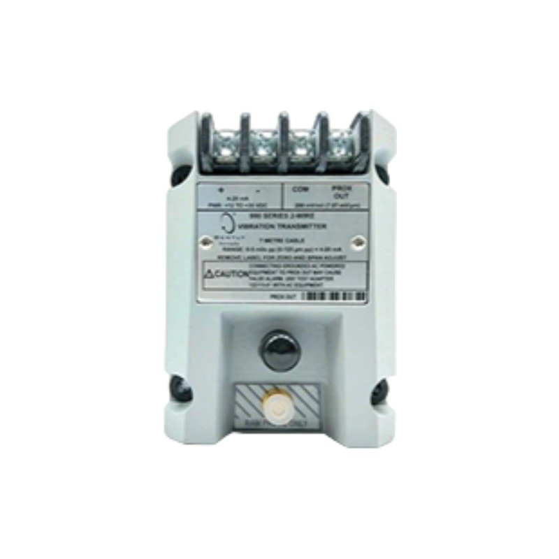
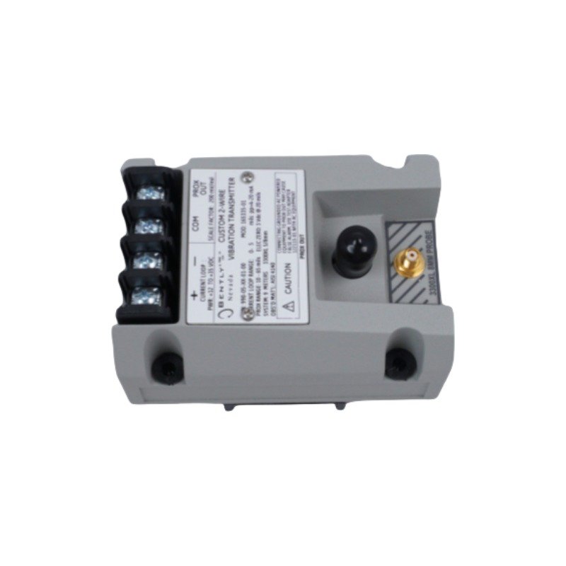
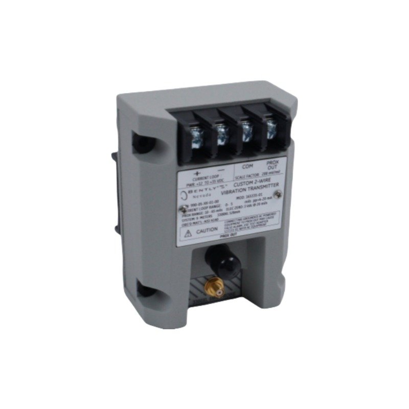
The Bently Nevada 284398-01, also cataloged as the 284398-01 991 Thrust Transmitter, operates as a dedicated hardware component for axial displacement signal conversion within Bently Nevada machinery monitoring systems. Specifically, it converts high-frequency electrical inputs from local proximity probes into a standardized analog current loop output. Therefore, the internal circuitry routes the modulated measurement values directly to external processing hardware or supervisory network topologies.
Hardware Specifications
Parameter
Specification
Model
284398-01
Brand
Bently Nevada
Product Type
991 Thrust Transmitter
Series
991 Series
Origin
USA
Weight
0.22 kg
Dimensions
88 mm x 35 mm x 70 mm
Operating Temp
-40 deg C to +85 deg C
Power Consumption
Loop powered 18 to 30 VDC supply
Input Signal
Proximity probe input
Output Signal
4-20 mA proportional axial displacement output
Measurement Range
Approximately +/- 1.0 mm
Accuracy
+/- 0.5% full scale
Probe System Compatibility
5 m or 7 m probe extension system
Signal Interface
Two-wire loop powered transmitter
Housing Protection
IP65
Mounting Type
Industrial field mounting
Eddy-Current Probe Scaling and Rotor Dynamics
The hardware design dictates precise eddy-current probe scaling to translate physical clearances into linear electrical variations. Consequently, the input circuit maintains strict calibration between the 3300 XL proximity probe system and the connected monitoring or control equipment. Proper gap voltage validation (-10 VDC targets) during baseline installation establishes the required reference point for accurate rotor position measurement. Furthermore, this calibrated scaling ensures that the transmitter captures sudden changes in rotor dynamics and axial movement, converting the raw sensor response directly into a stable 4-20 mA output signal.
Frequently Asked Questions
Q: How does the transmitter handle variations in loop supply voltage?
A: The transmitter utilizes an internal voltage regulator that maintains circuit stability across a loop supply range of 18 VDC to 30 VDC. Therefore, fluctuations within this operating envelope do not degrade measurement accuracy.
Q: Can the 284398-01 transmitter support hot-swapping while the 4-20 mA loop is active?
A: No. Field technicians must de-energize the external 18 to 30 VDC loop power supply before disconnecting or servicing the transmitter terminals to prevent signal corruption or electrical transients.
Q: What are the cable length restrictions for the input probe system?
A: The input circuitry matches specific electrical impedances. Consequently, the transmitter only supports configured 5 meter or 7 meter proximity probe and extension cable systems.
Field Installation Guidelines
Mounting Mechanics: Secure the transmitter housing to a flat surface or dedicated industrial mounting plate using the integrated mounting holes. Ensure that the installation location provides protection up to the IP65 rating limits and minimizes mechanical vibration.
Shielding Requirements: Route the probe lead-in wire and the 4-20 mA output loop wire through separate grounded metallic conduits. Connect the cable shields firmly to the system instrumentation ground bus bar at the receiver end only.
Wiring Separations: Maintain a minimum physical separation distance of 200 mm between the low-voltage transmitter signaling loops and any adjacent high-voltage AC electrical lines or heavy motor supply conductors.
Thermal Management: Verify that the local environmental temperature does not cross the operating threshold of -40 deg C to +85 deg C. Provide auxiliary sunshades or heat shields if the device sits near high-temperature mechanical components.
Additional information
Weight
0.22 kg
Dimensions
65 × 70 × 75 mm
0.0
Average Rating
Rated
(0 Reviews)
Rated
0%
Rated
0%
Rated
0%
Rated
0%
Rated
0%
Be the first to review “Bently Nevada 284398-01 991 Thrust Transmitter” Cancel reply











0.0 Average Rating Rated (0 Reviews)