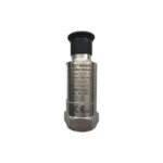
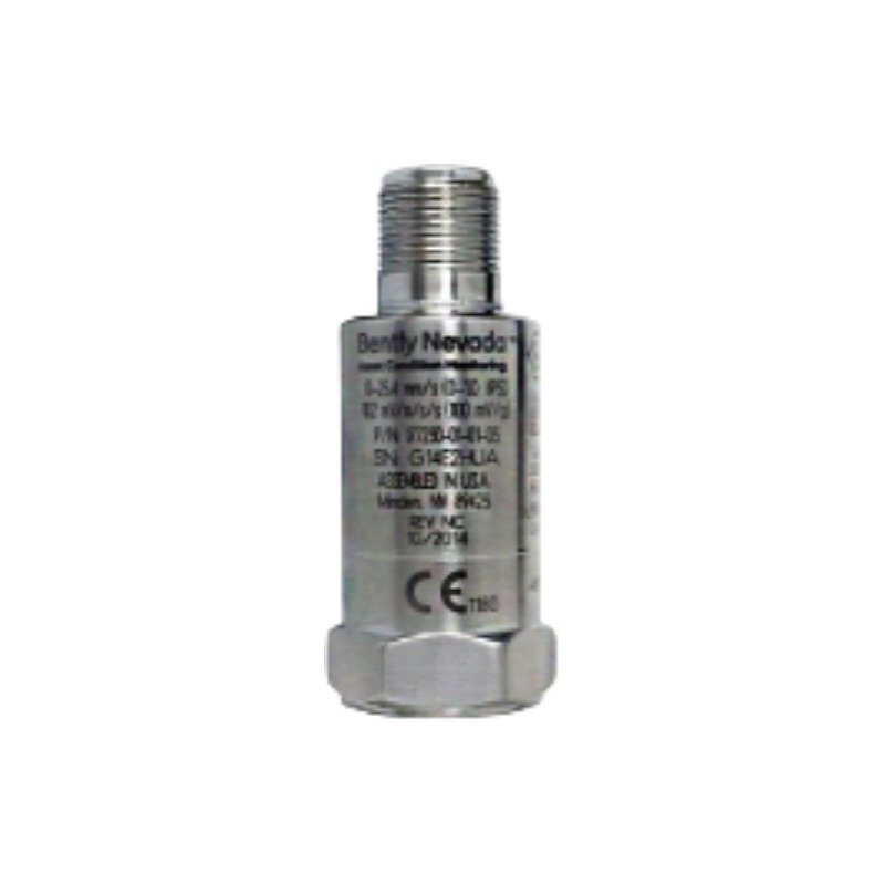
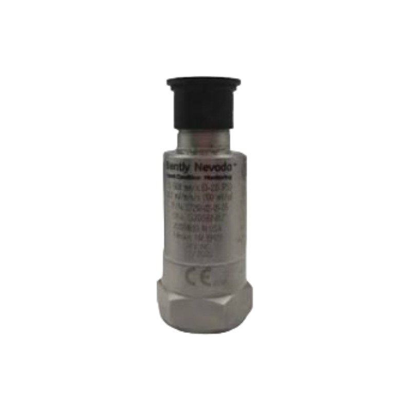
The Bently Nevada 177230-00-02-05 operates as a loop-powered 177230 Seismic Velocity Transmitter designed for basic protection and condition monitoring of general-purpose machinery. Specifically, the solid-state piezo-accelerometer hardware automatically integrates an internal acceleration signal into velocity vibration metrics and subsequently converts the physical vibrations into a linear 4-20 mA DC current loop. Consequently, this design executes the direct transmission of machinery casing vibration values straight to a programmable logic controller (PLC), distributed control system (DCS), or SCADA platform without requiring an intermediate monitoring rack or field configuration.
Hardware Specifications
Parameter
Specification
Model
177230-00-02-05
Brand
Bently Nevada
Origin
USA
Weight
131 g (4.62 oz) typical
Dimensions
25.4 mm (1.00 in) diameter x 66.0 mm (2.60 in) height
Operating Temp
-40 deg C to +85 deg C (-40 deg F to +185 deg F)
Case Material
316L Stainless Steel (Hermetically sealed)
Main Output
4-20 mA DC loop-powered proportional velocity vibration
Secondary Output
Unbuffered raw dynamic voltage waveform ($10.2\text{ mV/m/s}^2$ / $100\text{ mV/g}$ $\pm20\%$)
Frequency Response
3 Hz to 1 kHz (180 to 60 kcpm) $\pm10\%$ for primary loop
System Supply Voltage
12 to 30 VDC (Current limited to 40 mA)
Connection Type
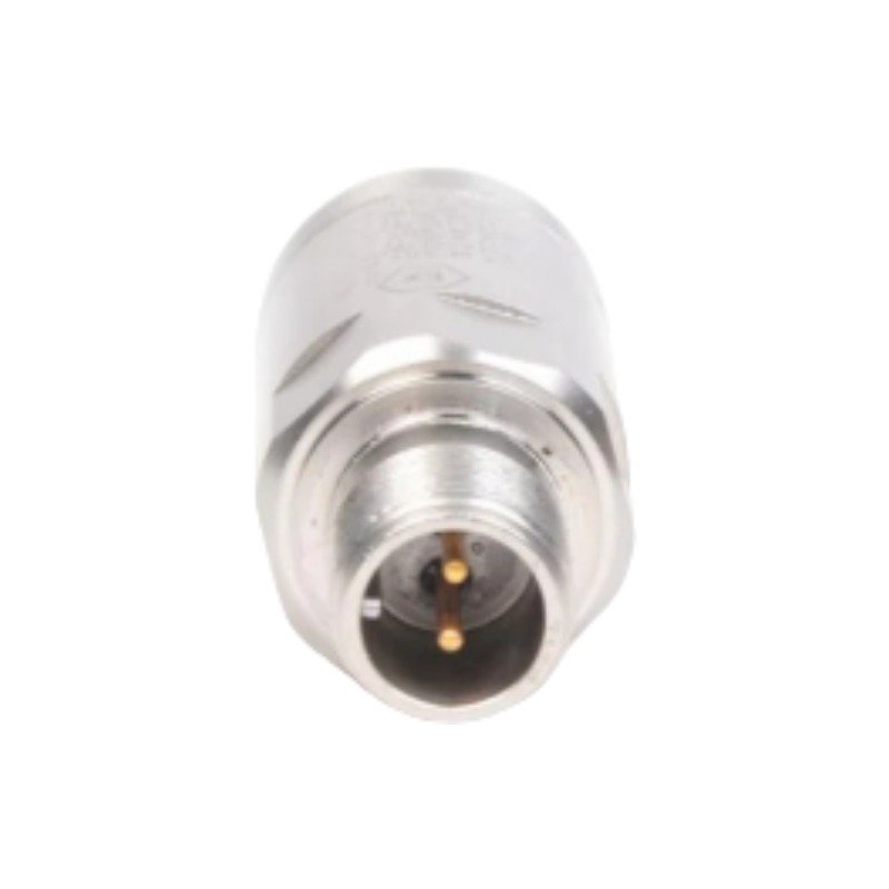
3-pin MIL-C-5015 top connector, 316L stainless steel
Transducer Dynamics and Signal Properties
The Bently Nevada 177230-00-02-05 incorporates dual-signal processing pathways inside its compact stainless steel capsule to satisfy both basic trending and detailed diagnostic requirements. The primary current loop (Signal One) delivers a steady state broadband value scaled directly to the full-scale velocity parameter. Concurrently, the unbuffered dynamic voltage output (Signal Two) passes a raw, high-frequency acceleration waveform to a non-sensor end patch panel, facilitating detailed roller-element bearing assessments via portable machinery analyzers.
Frequently Asked Questions
Q: What specific hardware variables do the “-00”, “-02”, and “-05” option codes define?
A: The first “-00” option code configures a standard full-scale measurement range of 0 to 12.7 mm/s (0 to 0.5 in/s) velocity. The second “-02” code designates a low-end extended frequency response window of 3 Hz to 1 kHz, calibrated for peak tracking (ideal for lower-speed balance of plant machinery like large cooling tower fans or blowers). The final “-05” suffix indicates multiple global hazardous area certifications (CSA, NRTL/C, ATEX, and IECEx approvals).
Q: Can the primary 4-20 mA loop be grounded at the field terminal box?
A: No. The dynamic signal return line (Pin B) serves as the common reference point for both the current loop and the unbuffered voltage path. If this terminal is accidentally connected to ground at the machine frame, the current loop will short-circuit, causing the transmitter output to drop to 0 mA.
Field Installation Guidelines
Shielding and Grounding: First, route a high-quality shielded 3-conductor cable using the MIL-C-5015 connector interface. Afterwards, ensure the cable shield is cleanly cut and insulated at the sensor head, bonding the drain wire exclusively at the PLC/DCS input module terminal strip to block ground loops.
Magnetic Base Precaution: When conducting periodic route monitoring via a magnetic base, do not “snap” the magnetic assembly vertically onto the machine structure. Instead, roll the magnetic base gently onto the target surface; this avoids extreme mechanical shock spikes capable of overwhelming or permanently fracturing the internal ceramic shear element.
Mechanical Torque Setup: Mount the transmitter casing flush against a clean, paint-free, unpainted structural surface machined flat to a fine finish. Thread the provided 1/4-28 UNF, M6, or M8 stud adapter into the casing base, then tighten the assembly using a calibrated torque wrench to between 4 and 7 N-m (35.4 to 62.0 in-lbf).
Additional information
Weight
0.131 kg
Dimensions
65 × 85 × 70 mm
0.0
Average Rating
Rated
(0 Reviews)
Rated
0%
Rated
0%
Rated
0%
Rated
0%
Rated
0%
Be the first to review “Bently Nevada 177230-00-02-05 Seismic Transmitter” Cancel reply












0.0 Average Rating Rated (0 Reviews)