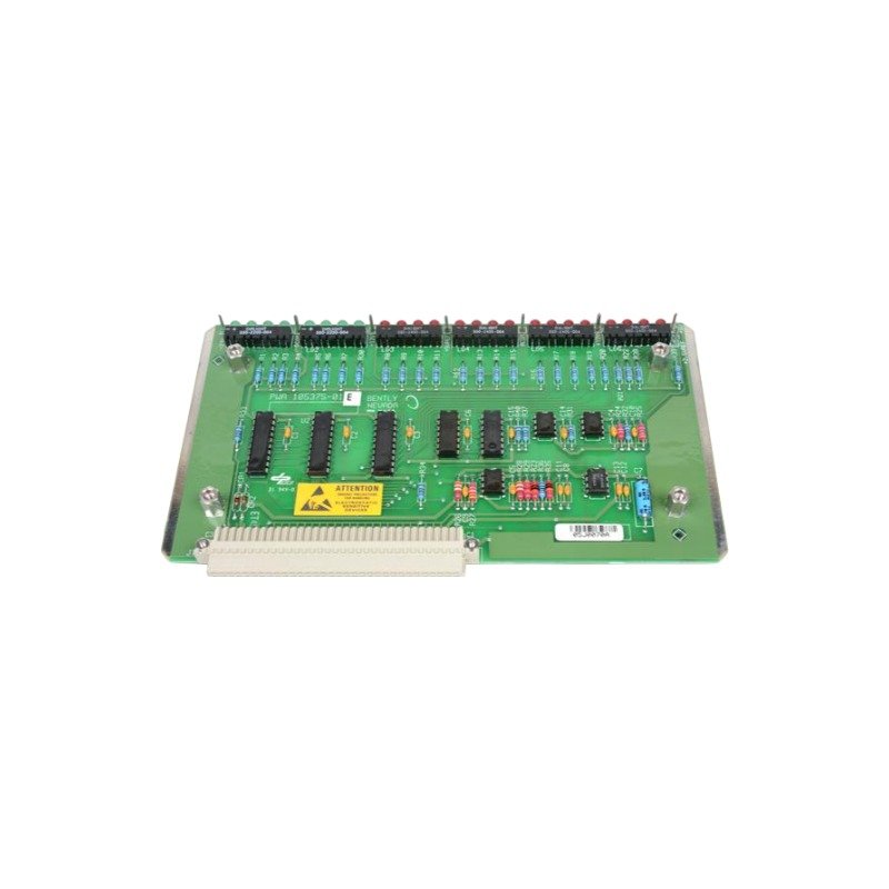
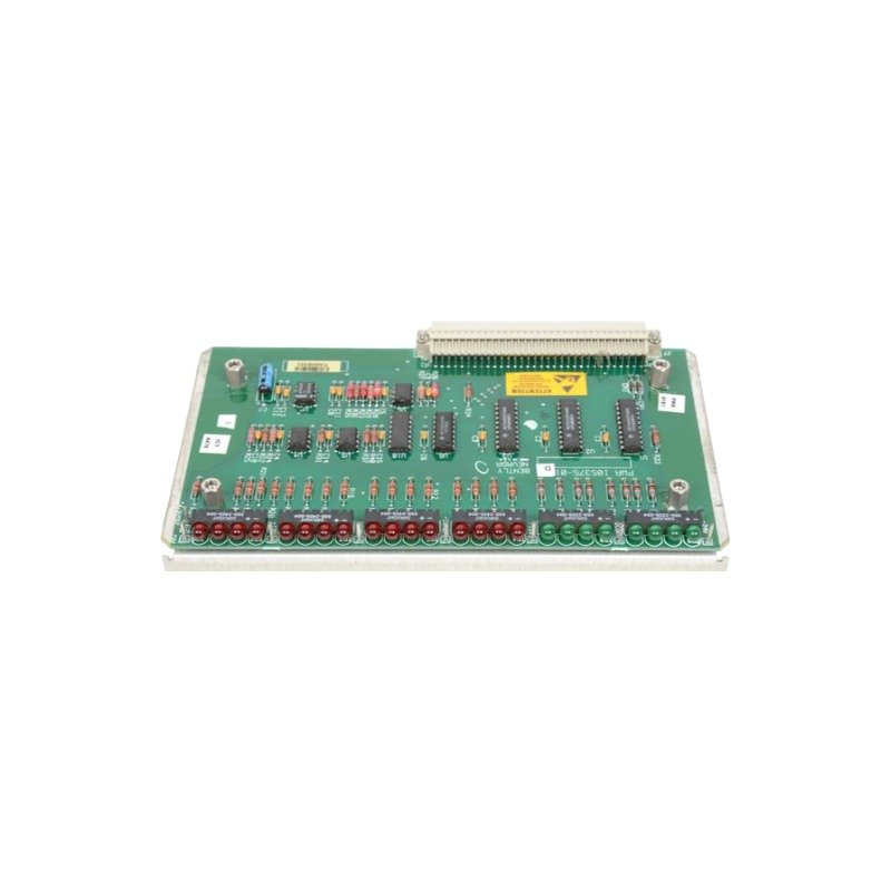
The Bently Nevada 105375-01 is an LED indicator board for the 3500/53 system featuring TDXnet connectivity. Brand New, Original Stock, Global Shipping.
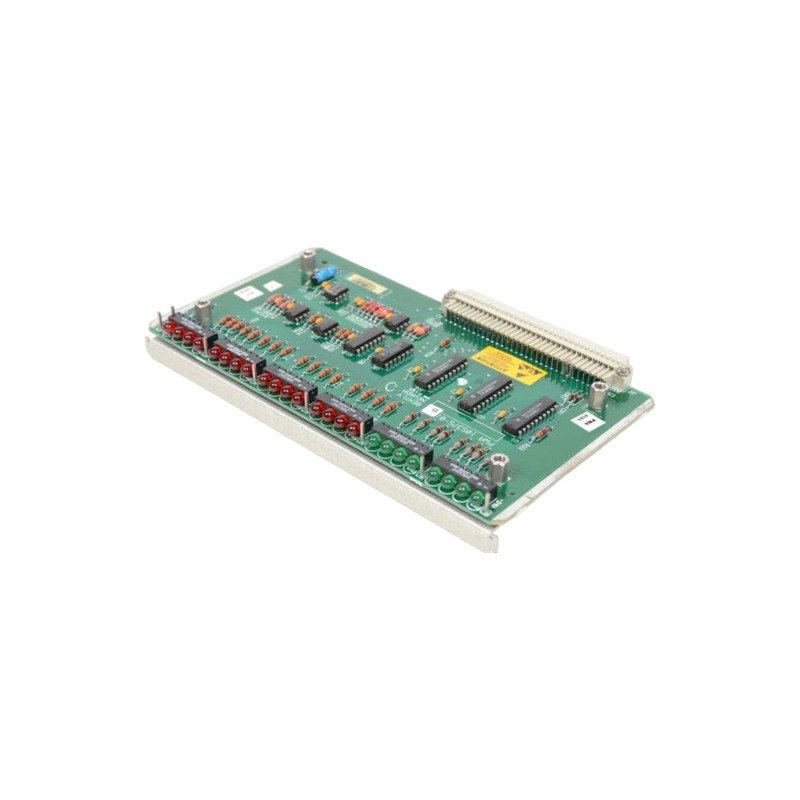
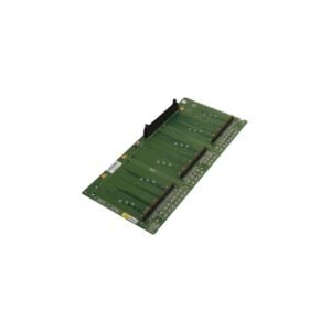
The Bently Nevada 105375-01 serves as the primary 105375-01 Light Board utilized to execute optical status feedback and diagnostic visualization across 3500/53 System platforms. Configured for local system instrumentation reporting, the board acts as the direct physical layout for displaying hardware states. It interfaces with system architectures via the TDXnet Transient Data Interface to correlate dynamic measurement values with visual panel arrays.
Hardware Specifications
Parameter
Specification
Model
105375-01
Brand
Bently Nevada
Origin
USA
Weight
0.45 kg typical
Dimensions
Standard 3500 series slot profile
Operating Temp
-30 deg C to +65 deg C
Power Consumption
3 W typical
Series
3500/53 System
Data Interface
TDXnet Transient Data Interface
Communication Link
Ethernet link to Data Manager
Buffering
Two independent startup/shutdown buffers
Machinery Monitoring and TSI Characteristics
The module structure works alongside core monitoring subsystems to process dynamic variables, capturing high-resolution static, orbit, and spectrum data for transient shaft analysis. The processing pipeline supports continuous signal evaluation, including gap voltage validation (-10 VDC targets) and eddy-current probe scaling across connected proximity channels. By tracking complex rotor dynamics during mechanical speed transitions, the internal memory arrays log data into two independent startup/shutdown buffers. Additionally, layout shielding maintains strict cross-talk suppression between adjacent visual drive lines and primary sensor inputs, ensuring that indicator power fluctuations do not corrupt dynamic machinery parameters.
Frequently Asked Questions
Q: How does the 105375-01 handle state transitions immediately following a system power disruption?
A: The hardware architecture is designed with internal state-retention elements that facilitate immediate recovery from power loss, minimizing local diagnostic downtime and preventing display state mismatching upon backplane power restoration.
Q: What network link provides transmission for the collected high-resolution transient datasets?
A: The hardware links directly via an internal Ethernet connection to the system Data Manager, allowing static, orbit, and spectrum variables to bypass standard processing loops for efficient upload to machinery management platforms.
Q: Can this component undergo hot-swap installation while the 3500 rack backplane is energized?
A: While the physical connectors accept insertion under load, technicians must activate the appropriate safety bypass controls within the host software matrix prior to mechanical installation to avoid generating spurious error flags.
Field Installation Guidelines
Mounting Mechanics: Insert the board assembly directly into its assigned alignment slot within the 3500/53 System chassis panel. Tighten all faceplate retention screws completely to establish secure backplane seating and consistent chassis ground path continuity.
Shielding Requirements: Route all external monitoring communication cables through continuous braided metal shields. Terminate the shield architecture exclusively at the main rack panel instrumentation earth bus bar to mitigate ambient electrical noise injection.
Wiring Separations: Maintain a structural path separation of at least 200 mm between local signal lines, Ethernet paths, and adjacent high-voltage power distribution cables or motor control loops.
Thermal Management: Verify that the localized ambient air temperature within the rack housing is maintained within the -30 deg C to +65 deg C limits. Check that forced-air ventilation patterns pass unobstructed across the front faceplate area.
Additional information
Weight
0.45 kg
Dimensions
65 × 75 × 56 mm
0.0
Average Rating
Rated
(0 Reviews)
Rated
0%
Rated
0%
Rated
0%
Rated
0%
Rated
0%
Be the first to review “Bently Nevada 105375-01 3500/53 Series Light Board” Cancel reply











0.0 Average Rating Rated (0 Reviews)