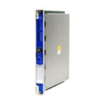
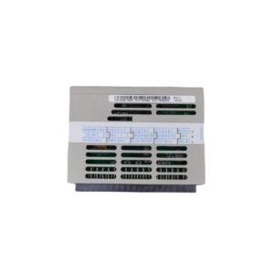
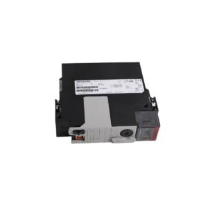
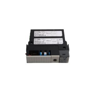
The Bently Nevada 3500/53, also cataloged as the 3500/53 Overspeed Detection Module, operates as a dedicated hardware component for emergency machinery safety shutdown execution within 3500 Series Machinery Protection System architectures. Configured to monitor rotational velocity profiles with extreme speed response attributes, the module continuously samples pulse frequency parameters from magnetic pickups or proximity sensors. The module executes independent internal trip logic calculations to deliver deterministic fail-safe output commands to dedicated relay elements when shaft velocity values exceed precise structural redline parameters.
Hardware Specifications
Parameter
Specification
Model
3500/53
Brand
Bently Nevada
Origin
USA
Weight
0.85 kg
Dimensions
241.3 mm x 24.4 mm x 241.8 mm
Operating Temp
-30 deg C to +65 deg C
Power Consumption
8.5 W typical baseline consumption from 3500 backplane
Channel Capacity
3 independent, redundant speed input channels
Input Signal Range
+30 V to -30 V peak-to-peak voltage threshold limits
Frequency Range
1.0 Hz to 30 kHz pulse execution limit
Trip Response Time
15 milliseconds or less execution latency
Eddy-Current Probe Scaling and Gap Voltage Validation
When paired with proximity probes for speed tracking, the 3500/53 module demands a standard eddy-current probe scaling configuration of 7.87 V/mm (200 mV/mil). During initial transducer setup, technicians perform gap voltage validation to ensure that target speed gear teeth or Keyphasor notches sit directly within the linear measuring sweep, aligning the static bias output to standard -10 VDC targets. The module incorporates integrated high-frequency filtering and cross-talk suppression networks to block inductive noise from neighboring power lines. This noise isolation prevents pulse edge distortion or false triggering caused by secondary rotor dynamics and axial shaft shunting, ensuring flawless pulse detection under rapid acceleration curves.
Frequently Asked Questions
Q: Can the 3500/53 overspeed detection card be hot-swapped while the main machinery protection rack power distribution bus is live?
A: Yes, this hardware module supports physical extraction and insertion under live power conditions. However, pulling the active overspeed card breaks the internal safety interlock logic loops, which drops the system into a fault status and can trip the associated 2oo3 voting relay logic if bypass keys are not engaged.
Q: How does the 3500/53 hardware execute its speed verification voting architecture?
A: The module utilizes a hardwired Triple Modular Redundant (TMR) 2oo3 voting architecture across its three internal channels. The module samples all three speed inputs simultaneously, and at least two channels must independently confirm an overspeed setpoint violation before the system commands a fail-safe state execution to output relays.
Field Installation Guidelines
Chassis Position Integration: Slide the 3500/53 card body along the upper and lower plastic guide rails of the designated front chassis slot. Press the module inward with steady pressure until the multi-pin backplane connector locks into the rack motherboard.
Transducer Grounding Continuity: Terminate the braided shields of all speed sensor lines directly at the dedicated shield ground lugs on the companion rear I/O module. Do not ground the shields at the local machine junction boxes to prevent the formation of measurement-degrading ground loops.
Cable Physical Bend Restraints: Maintain a strict minimum physical bending radius boundary of 25.4 mm (1.0 inch) across all sensor signal lines. Bending the lines beyond this radius alters core coaxial cable capacitance metrics and can deform the high-frequency pulse edge responses.
High-Voltage Track Isolation: Route all low-voltage overspeed signal cables inside dedicated, grounded metal conduit paths. Maintain a minimum physical spacing clearance of 152 mm (6.0 inches) away from parallel 3-phase AC power cables to block electromagnetic noise from injecting false speed pulses into the loop.
Additional information
Weight
0.7 kg
Dimensions
36 × 16 × 20 mm
0.0
Average Rating
Rated
(0 Reviews)
Rated
0%
Rated
0%
Rated
0%
Rated
0%
Rated
0%
Be the first to review “Bently Nevada 3500/53 Electronic Overspeed Detection System” Cancel reply


0.0 Average Rating Rated (0 Reviews)