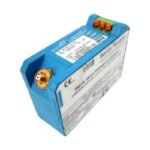
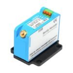
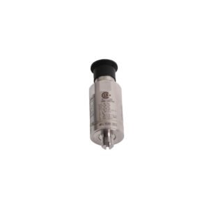
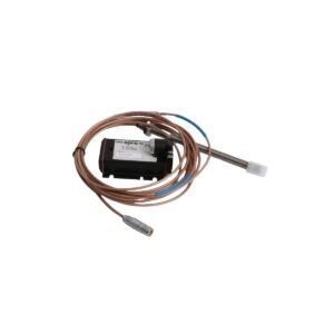
The Bently Nevada 330180-X0-00, also cataloged as the 330180 Proximitor Sensor, serves as the central signal conditioning module within a non-contacting 3300 XL 5mm or 8mm Proximity Transducer System. Specifically, this hardware component generates a high-frequency radio frequency (RF) signal that it feeds to the proximity probe tip, and then converts the resulting modulated eddy-current impedance variations into a clean, linear analog voltage output. Consequently, the unit transmits this continuous dynamic signal to 3300 or 3500 series machinery protection system backplanes for asset monitoring and safety shutdowns.
Suffix Breakdown & Model Matrix
330180: Core product identifier for the 3300 XL Proximitor Sensor module.
X0: Variable placeholder for total system electrical length and tube-mounting configuration. Common configurations include:
50: 5.0-meter total system length, standard panel-mount or DIN-rail base.
90: 9.0-meter total system length, standard panel-mount or DIN-rail base.
51: 5.0-meter total system length, configured with DIN-rail mount.
91: 9.0-meter total system length, configured with DIN-rail mount.
00: Agency approval option designating standard factory build certifications (including multi-country hazardous area certifications like ATEX, IECEx, and CSA).
00: ST (Threaded) connector option denoting standard coaxial connector profiles without specialized coaxial protective caps.
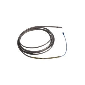
Pairs with standard 3300 XL 5mm & 8mm proximity probes
Frequency Response
DC to 10 kHz (-3 dB bandwidth)
Eddy-Current Probe Scaling and Rotor Dynamics
The 330180-X0-00 utilizes advanced RF bridge circuitry to drive the remote probe tip. During physical installation, technicians execute loop verification by confirming the DC gap voltage settles at a nominal -10 VDC baseline, which corresponds exactly to the center point of the calibrated 7.87 V/mm (200 mV/mil) scale factor curve. Furthermore, the specialized internal shielding and input circuitry provide substantial cross-talk suppression if technicians must arrange multiple Proximitor modules side-by-side inside a single terminal housing. To accurately capture high-frequency rotor dynamics, the module features a wide DC to 10 kHz response range with zero phase lag. This high-speed fidelity prevents micro-structural material variances or physical runout anomalies on the rotating shaft from introducing parasitic voltage distortion into the dynamic radial vibration or axial position monitoring signals.
Frequently Asked Questions
Q: How does a field engineer choose between the “50” and “90” system length choices for this module?
A: The choice depends on the physical distance between the probe tip installation location and the intermediate field junction box. A “50” option requires the combined physical length of the probe and extension cable to equal exactly 5.0 meters, while a “90” option requires a combined physical length of exactly 9.0 meters. The Proximitor must match the cable length to preserve the integrity of the calibrated impedance loop.
Q: What action does the Proximitor take if a field transducer wire shorts out or the probe tip is ground-contacted?
A: The sensor features an integrated self-diagnostic circuit. If the probe cabling open-circuits, short-circuits, or drifts outside the calibrated window, the output voltage drops outside the valid monitoring band (typically moving closer to 0 VDC or exceeding -20 VDC). The upstream 3500 monitor identifies this as a “Not OK” status and safely locks out emergency trip logic for that channel.
Field Installation Guidelines
Base Rails and Enclosure Mounting: Mount the Proximitor onto a flat sub-panel surface or snap it onto a 35 mm standard DIN-rail frame, depending on the base clip option selected. Ensure that the metal casing of the Proximitor remains electrically isolated from the structural enclosure backplate to block ground noise loops.
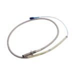
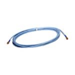
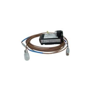
ClickLoc Interconnection Sequence: Align the miniature coaxial ClickLoc fitting from the extension cable with the Proximitor sensor receptacle. Push the sleeve forward firmly until it locks with an audible click. Slide an approved connector insulation sleeve or connector protector over the interface seam to keep out ambient dirt and moisture.
Signal Core Terminal Connections: Terminate the field signal wires using a three-wire shielded cable (comprising VT, OUT, and COM lines) hooked into the screw-terminal blocks. Torque the screws to a maximum of 0.5 N-m (4.4 in-lb) and terminate the outer shield drain wire exclusively at the monitor rack chassis ground.
Additional information
Weight
0.6 kg
Dimensions
26 × 16 × 22 mm
0.0
Average Rating
Rated
(0 Reviews)
Rated
0%
Rated
0%
Rated
0%
Rated
0%
Rated
0%
Be the first to review “Bently Nevada 330180-X0-00 3300 XL Proximitor Sensor” Cancel reply


0.0 Average Rating Rated (0 Reviews)