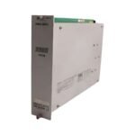
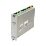
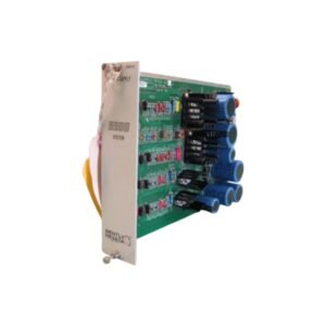
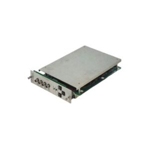
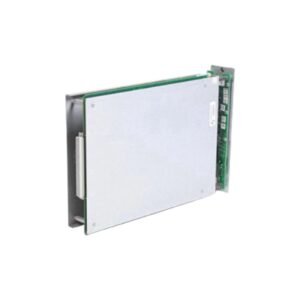
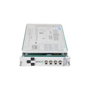
Configured for non-contacting vibration, thrust, and shaft position measurement tasks in 3300 Machinery Monitoring System racks, the Bently Nevada 3300/14, also cataloged as the 3300/14 Proximity Transducer Interface Module, provides direct physical/electrical execution. This hardware component processes raw dynamic input signals from proximity probe and Proximitor systems before routing conditioning data over the proprietary backplane architecture.
Hardware Specifications
Parameter
Specification
Model
3300/14
Brand
Bently Nevada
Origin
USA
Weight
0.85 kg
Dimensions
Slot width: 1-slot wide card for 3300 rack
Operating Temp
0 to 65 deg C
Power Consumption
4.5 W typical
Transducer Compatibility
3300 5 mm, 8 mm, and 7200 5 mm, 8 mm proximity transducer systems
Input Channels
2 independent channels
Output Signal Range
-2 to -18 VDC proportional to displacement
Eddy-Current Probe Scaling and Gap Voltage Validation
The module incorporates precise hardware potentiometers to guarantee accurate eddy-current probe scaling across compatible transducer systems. During commissioning, loop calibration dictates verification of the gap voltage validation (-10 VDC targets) within the linear range of the calibration curve to prevent saturation. Cross-talk suppression circuitry minimizes electromagnetic and capacitive interference between closely spaced adjacent proximity probes, stabilizing the raw RF carrier modulation. The low-noise analog construction mitigates false alarms from high-frequency electrical interference, preserving rotor dynamics waveforms for transient and steady-state vibration analysis.
Frequently Asked Questions
Q: What is the mandatory target value for the gap voltage validation during probe positioning?
A: The field installation manual mandates a nominal -10 VDC gap voltage target, corresponding to the midpoint of the linear range for standard 8 mm eddy-current proximity probes.
Q: Can the 3300/14 module be inserted or removed while the 3300 monitoring rack is powered up?
A: No, this module does not support live-insertion or hot-swap procedures. Power down the rack mainframe prior to inserting or removing the module to prevent electrical overstress to the backplane.
Q: How does cross-talk suppression function within this specific module assembly?
A: Cross-talk suppression is maintained via internal ground plane shielding and filtering on the differential input stages, preventing signal bleed-through when transducers are routed within the same conduit.
Field Installation Guidelines
Shield Grounding Continuity: Terminate the coaxial or twisted-pair outer shields strictly at the chassis ground block of the 3300 rack. Do not ground the shield at the transducer terminal box to eliminate ground loops.
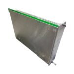
Backplane Seating Verification: Slide the module along the chassis guide rails until the rear Eurocard connectors seat firmly into the backplane matrix. Secure the top and bottom captive screws to ensure continuous ground contact.
Conduit Segregation Constraints: Maintain a physical separation barrier of at least 300 mm between the transducer field wiring and high-voltage AC motor supply cables to eliminate inductive noise coupling.
Additional information
Weight
0.8 kg
Dimensions
32 × 16 × 16 mm
0.0
Average Rating
Rated
(0 Reviews)
Rated
0%
Rated
0%
Rated
0%
Rated
0%
Rated
0%
Be the first to review “Bently Nevada 3300/14 Dual Driver/Receiver Proximity Transducer Interface Module” Cancel reply


0.0 Average Rating Rated (0 Reviews)