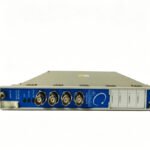
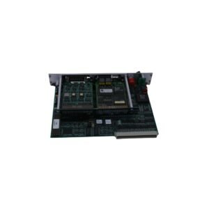
The Bently Nevada 176449-04, also cataloged as the Bently Nevada 176449-04 Position Monitor Module, operates as a dedicated hardware component for continuous machinery protection and absolute shaft position tracking within Bently Nevada 3500 Series Machinery Protection System networks.
The module executes real-time eddy-current probe scaling and calibration validation across all connected input channels. Simultaneously, the internal hardware configuration continuously monitors the incoming DC gap voltage to verify precise sensor positioning relative to the target shaft. Specifically, the module enforces a strict gap voltage validation target of -10 VDC to confirm that the transducer operates within its linear measurement range. Consequently, if the gap voltage drifts outside these designated thresholds, the module flags a channel error condition. This immediate action mitigates the risk of inaccurate rotor dynamics evaluation and enhances cross-talk suppression between tightly grouped transducer wiring runs.
Frequently Asked Questions
Q: Which transducer types can connect directly to the 176449-04 hardware interface?
A: The module accepts direct inputs from proximity sensors, Rotary Position Transducers (RPTs), AC or DC Linear Variable Differential Transformers (LVDTs), and standard rotary potentiometers.
Q: How does the module handle signal updates for high-priority protective loops?
A: The internal microprocessor updates all processed channels and measured variables in 100 ms or less, thereby ensuring immediate output responses to sudden mechanical position shifts.
Field Installation Guidelines
Chassis Alignment Protocol: Insert the module into any standard monitoring slot of the 3500 chassis. First, verify alignment with the upper and lower plastic card guides, and then apply firm, steady pressure until the rear connectors mate completely with the backplane.
Shield Grounding Framework: Terminate all coaxial and multi-conductor sensor shields exclusively at the designated 3500 internal termination bulkhead or external termination block. However, do not connect the shield at the sensor end to avoid creating localized ground loop circuits.
Terminal Block Fastening: Tighten all field wiring connection screws on the I/O interface to a regulated torque value between 0.56 and 0.79 N-m. As a result, this continuous clamping force prevents intermittent contact failure induced by high-amplitude machinery vibration.
Additional information
Weight
1 kg
Dimensions
20 × 36 × 22 mm
0.0
Average Rating
Rated
(0 Reviews)
Rated
0%
Rated
0%
Rated
0%
Rated
0%
Rated
0%
Be the first to review “Bently Nevada 176449-04 3500/45 Position Monitor Module” Cancel reply


0.0 Average Rating Rated (0 Reviews)