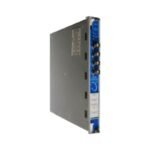
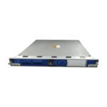
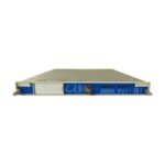
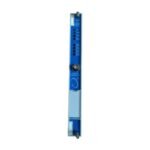
The Bently Nevada 133388-01, also cataloged as the 133388-01 Electronic Overspeed Detection Module, serves as the primary 3500/53 Overspeed Protection component utilized to execute real-time shaft velocity monitoring and emergency trip functions across 3500 Machinery Protection System platforms. This module evaluates transducer inputs continuously to identify overspeed and underspeed conditions. It triggers internal relay circuits within milliseconds when a velocity threshold breach occurs, operating as a standalone highly reliable hardware loop independent of main rack communication processors.
Hardware Specifications
Parameter
Specification
Model
133388-01
Brand
Bently Nevada
Origin
United States
Weight
0.82 kg
Dimensions
241.3 mm x 24.4 mm x 103.1 mm
Operating Temp
-30 to +65 deg C
Power Consumption
8.0 W typical
Input Signal Options
Proximity probes, Magnetic pickups
Response Time
Less than 15 milliseconds
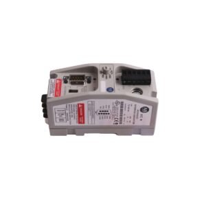
Output Interface
Buffered transducer front panel BNC, Backplane relay logic
Isolation
500 Vrms galvanic isolation
Rotor Dynamics and Eddy-Current Probe Scaling
The Bently Nevada 133388-01 interfaces directly with high-frequency speed sensors to map rotor dynamics during critical startup, steady-state, and coast-down phases. The hardware accommodates precise eddy-current probe scaling, converting physical target transitions into clean digital pulse trains. To guarantee execution stability on high-speed turbines, internal algorithms execute cross-talk suppression to isolate speed signals from adjacent vibration channels on the backplane. The module constantly monitors gap voltage validation, verifying that sensor positioning matches designated -10 VDC targets to ensure continuous speed-loop integrity and eliminate false trip commands.
Frequently Asked Questions
Q: What is the exact purpose of the front-panel BNC connector on the 133388-01 module?
A: The front panel features a single BNC connector that delivers a buffered transducer signal. This connection allows field technicians to attach external oscilloscopes or data analyzers directly to the active speed sensor input without interrupting the online overspeed protection logic.
Q: Can the 133388-01 operate in a redundant configuration to prevent single-point failures?
A: Yes. The 3500/53 system utilizes these modules in a 2oo2 or 2oo3 voting architecture. Multiple 133388-01 modules link across the rack backplane to form a combined voting circuit, maximizing machinery safety while preventing spurious trips caused by a single sensor fault.
Field Installation Guidelines
Mount the module firmly into any available monitor slot of the 3500 rack chassis, excluding slots reserved for the Power Supply and Transient Data Interface modules.
Hand-tighten the upper and lower chassis thumbscrews, then torque them to 0.6 N m to achieve solid ground contact with the system frame.
Terminate the field transducer wiring at the rear I/O module, ensuring that the outer coaxial shields connect to the specified instrument ground bus.
Separate all speed sensor signal runs from heavy power distribution conduits to block electromagnetic interference from disrupting the frequency pulse verification.
Additional information
Weight
0.8 kg
Dimensions
26 × 18 × 12 mm
0.0
Average Rating
Rated
(0 Reviews)
Rated
0%
Rated
0%
Rated
0%
Rated
0%
Rated
0%
Be the first to review “Bently Nevada 133388-01 3500/53 Electronic Overspeed Detection Module” Cancel reply


0.0 Average Rating Rated (0 Reviews)