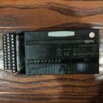
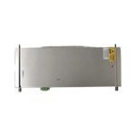
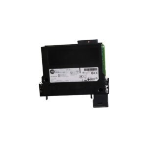
The Bently Nevada 125680-01, also cataloged as the 125680-01 Proximitor I/O Module, operates as a dedicated hardware component for processing machinery protection data within the 3500 Monitoring System chassis. Specifically, this module interfaces the external field transducers directly with the main 3500/40M Proximitor Monitor card. Consequently, the hardware routes raw multi-channel proximity signals through internal termination networks, supplying the backplane motherboard with stable data for real-time alarm valuation and logic voting.
Hardware Specifications
Parameter
Specification
Model
125680-01
Brand
Bently Nevada
Origin
United States
Weight
0.38 kg
Dimensions
25 mm x 114 mm x 241 mm
Operating Temp
-30 deg C to +65 deg C
Power Consumption
Passive card path (main power drawn via front monitor module)
Channel Density
4 independent input channels
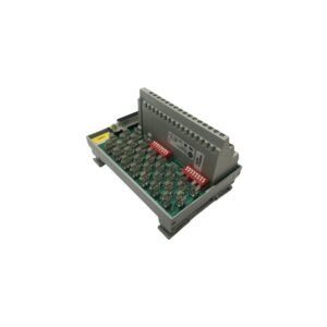
Termination Style
Internal terminations via terminal strip block
Input Impedance
10 kOhm standard proximity input line rating
Transducer Support
3300 XL 8 mm, NSv, and standard proximity systems
Mounting Type
Rear chassis plug-in slot configuration
Eddy-Current Probe Scaling and Rotor Dynamics
The 125680-01 channels high-frequency radio signals directly from connected eddy-current probes into the 3500 rack environment. During commissioning, technicians perform gap voltage validation across the internal terminal strip to maintain a static -10 VDC baseline position. This step secures steady sensor calibration tracking against the standard 7.87 V/mm (200 mV/mil) scale factor curve. Furthermore, the localized ground tracing layout provides substantial cross-talk suppression when engineering designs require mounting multiple eddy-current probes in close physical proximity inside a single bearing block housing. Meanwhile, precise capture of high-frequency rotor dynamics relies on clean input loops. The shielded backplane routing on this I/O module prevents electromagnetic noise induction, ensuring that micro-structural variations on the rotor shaft appear clearly without parasitic voltage signals altering the vibration trends.
Frequently Asked Questions
Q: How does the internal termination layout on this I/O card alter field wiring compared to external termination designs?
A: The internal termination design allows field engineers to wire the proximity probe transducer leads directly to the screw terminal strips built onto the rear faceplate of the 125680-01. This configuration eliminates the need for external terminal blocks or separate interface multi-conductor cables.
Q: Can an instrument technician live-swap the rear 125680-01 I/O module while the front 3500/40M monitor remains powered?
A: No, technicians must power down the slot cluster or the entire 3500 rack chassis before replacing the rear I/O module. Pulling the module while live causes sudden circuit breaking across the backplane terminals, which can trip false machinery alarms or damage the front processor logic.
Field Installation Guidelines
Chassis Slot Seating: Align the I/O module with the designated vertical guide slot at the rear of the 3500 rack frame, directly behind the matching 3500/40M monitor card. Push the card forward until the edge connector snaps fully into the motherboard socket, then tighten the top and bottom retaining screws to 0.5 N-m (4.4 in-lb).
Field Wire Termination and Insulation: Strip the proximity sensor field wires exactly 7 mm (0.28 in) back from the conductor tip. Insert the bare wire fully into the terminal clamp screw, then torque the screw to 0.5 N-m (4.4 in-lb) maximum to prevent stripping the threads. Maintain uniform wire twists up to the terminal clamp to minimize electromagnetic induction.
Shield Grounding Protocols: Terminate the outer shield drain wire of the Proximitor signal cable into the specified ground terminal terminal position on the I/O block. Technicians must ensure that the shield maintains a single-point connection back to the instrument chassis earth, keeping the field probe housing end floating to prevent parasitic ground loops.
Additional information
Weight
0.55 kg
Dimensions
32 × 16 × 12 mm
0.0
Average Rating
Rated
(0 Reviews)
Rated
0%
Rated
0%
Rated
0%
Rated
0%
Rated
0%
Be the first to review “Bently Nevada 125680-01 3500/40M Proximitor I/O Module” Cancel reply


0.0 Average Rating Rated (0 Reviews)