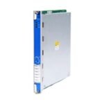
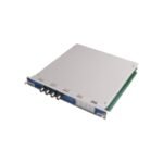
The Bently Nevada 125672-02, also cataloged as the Bently Nevada 125672 Keyphasor Module, operates as a dedicated hardware component for processing pulse signals from proximity probes or magnetic pickups within the 3500 Series Machinery Protection System backplane.
Hardware Specifications
Parameter
Specification
Model
125672-02
Brand
Bently Nevada
Origin
USA
Weight
0.45 kg
Dimensions
241 mm x 24 mm x 103 mm
Operating Temp
-30 to +65 deg C
Power Consumption
4.5 W maximum
Signal Input
Accepts 1 to 4 Keyphasor transducer signals
Input Impedance
21.5 kOhm minimum
Transducer Conditioning and Gap Voltage Validation
The module performs real-time conditioning of voltage pulses received from proximity sensor systems. During configuration setup, field engineers must execute a gap voltage validation target of -10 VDC to position the eddy-current probe within the linear range of the calibration curve. This voltage setting prevents clipping of the transient signal and stabilizes the trigger threshold logic. Accurate scaling ensures that rotor dynamics measurements, including shaft rotational speed and phase angles, are extracted without phase lag or trigger jitter, maintaining loop integrity across varying machine speeds.
Frequently Asked Questions
Q: Does the 125672-02 module support hot-swap replacement while the chassis is energized?
A: Yes. The module is engineered for online insertion and removal (OIR) within the 3500 rack frame. The internal power-limiting circuits prevent backplane voltage dips or damage to adjacent monitoring cards during a live swap.
Q: What are the input signal limits for magnetic pickups connected to this card?
A: The input circuitry accommodates passive magnetic pickup signals exceeding 1 Hz with a peak-to-peak amplitude greater than 2 V, up to a maximum peak voltage threshold of 90 V.
Field Installation Guidelines
Ensure the 3500 rack chassis is bonded to the local instrument ground grid using a heavy-gauge copper conductor before terminating field cables.
Route all transducer wiring in dedicated, grounded steel conduits to minimize electromagnetic interference from adjacent high-voltage motor lines.
Maintain the outer shield braid termination at the instrument rack end only; leave the sensor end ungrounded to eliminate ground loop current induction.
Verify that the physical keying pins on the back of the slot align correctly with the chassis connectors to prevent mechanical binding during insertion.
Additional information
Weight
0.77 kg
Dimensions
38 × 55 × 96 mm
0.0
Average Rating
Rated
(0 Reviews)
Rated
0%
Rated
0%
Rated
0%
Rated
0%
Rated
0%
Be the first to review “Bently Nevada 125672-02 3500 Series” Cancel reply


0.0 Average Rating Rated (0 Reviews)