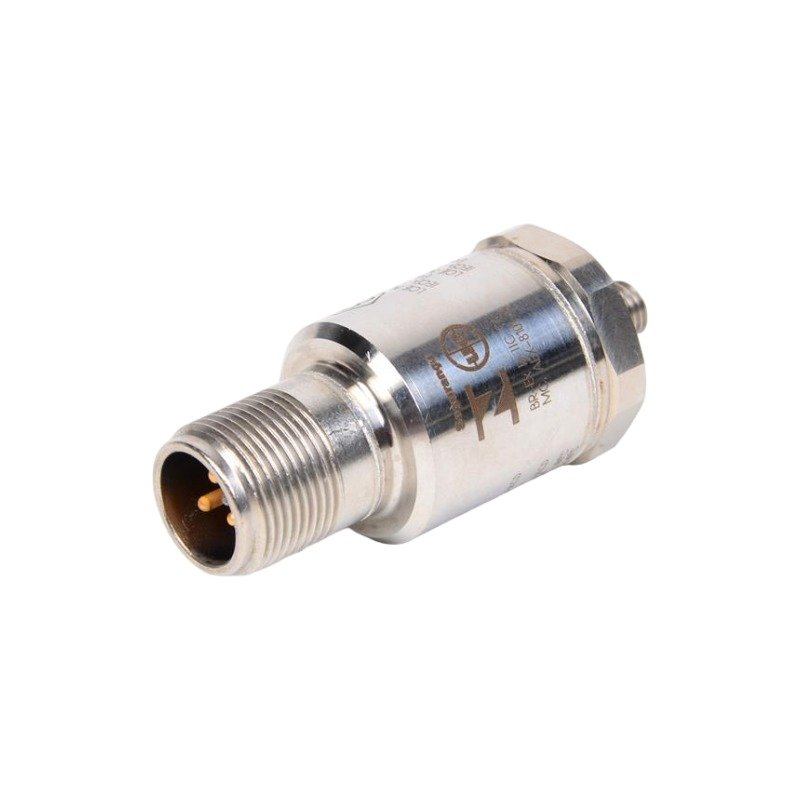
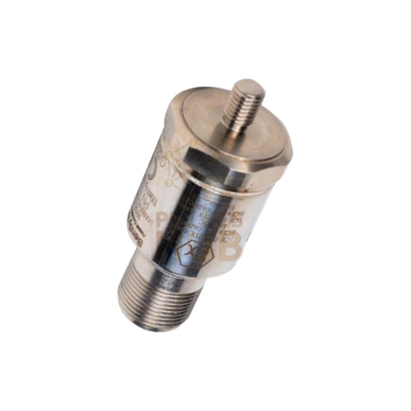
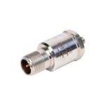
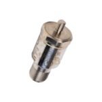
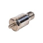
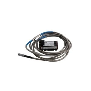
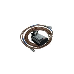
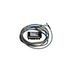
The Bently Nevada 330425-02-00 (330425 Accelerometer) provides direct physical and electrical execution for casing vibration measurement in machinery monitoring systems. Specifically, the component converts mechanical acceleration forces into proportional electrical signals, which then transmit to processing monitors to enable structural and rotational dynamic validation across machine platforms.
Suffix Breakdown & Model Matrix
The 330425 matrix defines mounting interface and hazard zone protection capabilities via the following selection criteria:
Operating within the Bently Nevada asset protection architecture, this accelerometer provides raw vibration acceleration metrics to evaluate structural casing transmission. Consequently, the sensor housing utilizes integrated cross-talk suppression methodologies to minimize multi-axis structural cross-contamination. Furthermore, while complementary displacement loops require gap voltage validation (-10 VDC targets) and explicit eddy-current probe scaling coefficients, this unit delivers high-frequency spectral tracking to diagnose high-speed rotor dynamics anomalies, bearing structural faults, and mechanical casing shocks.
Frequently Asked Questions
Q: How does the connection interface of the 330425-02-00 maintain shield continuity?
A: The sensor features an isolated internal design. As a result, the unit separates the signal lines and shield from the outer stainless steel housing block, which effectively prevents ground-loop contamination at the machine mounting location.
Q: Can an alternate mounting configuration be forced if the M8 x 1 thread strips in the field?
A: No, option code AA: 02 explicitly defines the mounting configuration as an integral stud. Therefore, modifying the integrated stud directly compromises the calibrated frequency response range and the mechanical coupling of the hardware.
Field Installation Guidelines
Mechanical Torquing & Thread Engagement: First, ensure the mounting surface is flat and free of debris. Next, torque the sensor to standard industrial specifications for M8 hardware to secure full thread engagement without distorting the internal piezoelectric crystals.
Casing Alignment: Always position the unit precisely perpendicular to the targeted axis of measurement. If misalignment occurs, the angular deviation induces transverse sensitivity errors and alters the accuracy of structural vibration data.
Shielding and Grounding: Terminate the outer cable shield at a single node within the instrument enclosure terminal block. Meanwhile, isolate the shield at the sensor head to eliminate electrical potential differentials.
Conduit Routing: Finally, deploy flexible conduit pathways immediately adjacent to the sensor housing. This arrangement safely accommodates mechanical displacement and high-frequency vibrations without putting tension on the cable connector body.
Additional information
Weight
0.10 kg
Dimensions
60 × 70 × 75 mm
0.0
Average Rating
Rated
(0 Reviews)
Rated
0%
Rated
0%
Rated
0%
Rated
0%
Rated
0%
Be the first to review “Bently Nevada 330425-02-00 330425 Accelerometer” Cancel reply












0.0 Average Rating Rated (0 Reviews)