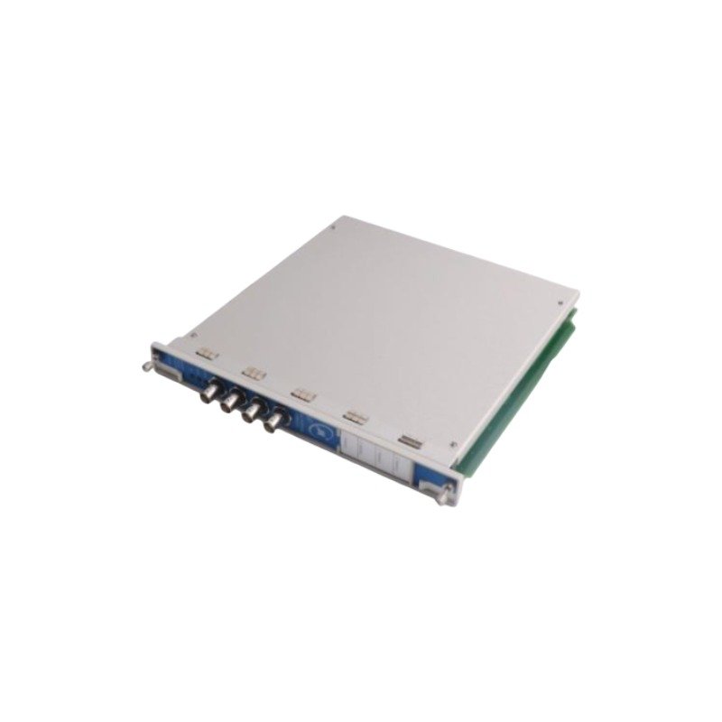
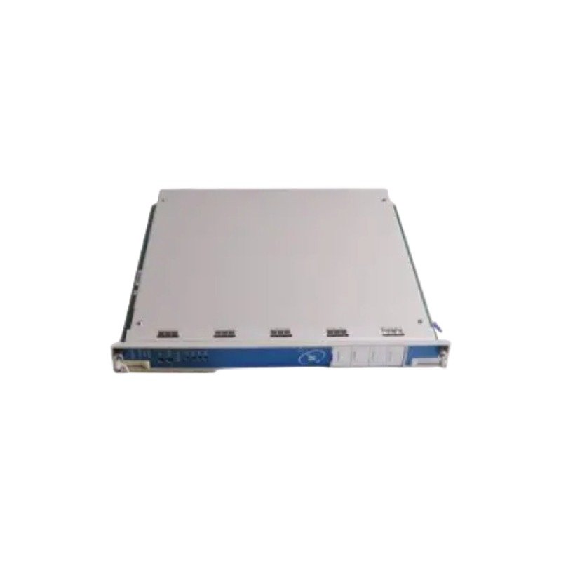
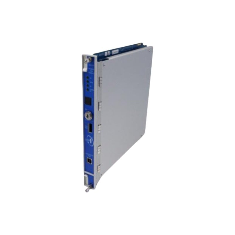
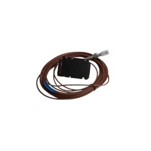
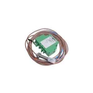
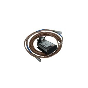
Configured for Specific Technical Task in Bently Nevada 3300 XL series, the Bently Nevada 285592-01 (285592-01 Proximitor Sensor) provides direct physical/electrical execution. Specifically, this sensor converts the physical gap between an eddy-current probe tip and a target conductive surface into a proportional analog voltage output. Consequently, the hardware passes the modulated electrical signals directly to monitoring rack systems across designated measurement networks.
Hardware Specifications
Parameter
Specification
Model
285592-01
Brand
Bently Nevada
Origin
USA
Weight
0.25 kg
Dimensions
81.3 mm x 61.2 mm x 63.5 mm
Operating Temp
-51 deg C to +100 deg C
Power Consumption
-24 VDC
Output Voltage
-18 VDC to -24 VDC
Frequency Response
0 to 10 kHz
Cable Length
9 meters
Machinery Monitoring and TSI Characteristics
The internal signal circuitry executes linear eddy-current probe scaling across the calibrated target range. Therefore, the device maintains gap voltage validation (-10 VDC targets) during static operation to confirm baseline mechanical alignment. Furthermore, the 10 kHz frequency response envelope captures high-frequency rotor dynamics fluctuations without signal phase lag. In addition, the hardware enclosure utilizes specific grounding paths to achieve cross-talk suppression, preventing mutual inductive interference when fields from adjacent proximity networks overlap.
Frequently Asked Questions
Q: What input power configuration does the 285592-01 Proximitor Sensor require for operation?
A: The hardware requires a constant -24 VDC input voltage. The connected monitoring rack or an external power distribution unit must supply this negative voltage via the power terminal connections.
Q: Does this hardware configuration support hot-swap replacement during system operation?
A: No. Technicians must de-energize the associated power supply circuit before disconnecting or replacing the sensor to prevent transient electrical spikes from affecting the monitoring network.
Q: How does the integrated 9 meters cable length affect loop calibration?
A: The device requires matching total system electrical lengths. Consequently, field personnel must pair this 9 meters unit only with the matching 3300 XL probe and extension cable configurations specified by the system design matrix.
Field Installation Guidelines
Mounting Mechanics: Secure the sensor housing onto a standard DIN-rail system or bolt it directly to a clean, unpainted metallic enclosure backing plate. Ensure that the mounting hardware achieves clean metallic contact to establish a solid case ground loop.
Shielding Requirements: Route the coaxial extension cables through dedicated, isolated conduits. Connect the outer shield layers firmly at the monitoring rack bulkhead ground bar, while keeping the sensor end floating to eliminate ground loops.
Wiring Separations: Maintain a physical clearance distance of at least 200 mm between the sensor signal cables and all adjacent AC power distribution or variable speed drive output cabling lines.
Thermal Management: Verify through environmental measurement that the localized sensor location does not exceed the operational envelope of -51 deg C to +100 deg C. Do not mount the device directly against uninsulated high-temperature steam pipe boundaries.
Additional information
Weight
0.25 kg
Dimensions
68 × 70 × 75 mm
0.0
Average Rating
Rated
(0 Reviews)
Rated
0%
Rated
0%
Rated
0%
Rated
0%
Rated
0%
Be the first to review “Bently Nevada 285592-01 Proximitor Sensor” Cancel reply












0.0 Average Rating Rated (0 Reviews)