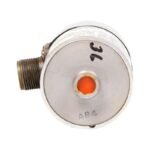
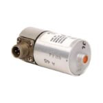
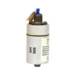
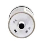
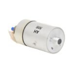
Configured for casing vibration measurement in industrial rotating machinery, the Bently Nevada 16699-03-02-02 (16699 Velocity Seismoprobe) provides direct physical/electrical execution.
Eddy-Current Probe Scaling and Gap Voltage Validation
Because this moving-coil velocity transducer operates passively, it generates its own raw voltage signal directly proportional to casing velocity without utilizing external proximitor drivers. Consequently, during multi-sensor commissioning alongside proximity probes, technicians execute gap voltage validation to eliminate signal contamination on the shared machinery protection rack. The internal architecture of the transducer suppresses cross-talk between high-frequency transmission paths, which directly prevents phase anomalies that distort local rotor dynamics evaluation. Furthermore, the 3500/42M or 3300 monitor modules scale the incoming calibration profiles according to the 500 mV/in/sec factory sensitivity, converting the mechanical case velocity into clear diagnostic variables without tracking a -10 VDC DC bias voltage.
Frequently Asked Questions
Q: Does the 16699-03-02-02 transducer require an external DC power supply to generate the vibration signal?
A: No, the sensor utilizes an internal moving-coil design that generates an analog voltage output purely from mechanical motion, which entirely eliminates the need for external loop power.
Q: What happens if field technicians install this specific module at a vertical (0-degree) angle relative to the machine surface?
A: Installing this module outside its designated 90 deg +/-2.5 deg horizontal operational window degrades the frequency response and calibration accuracy because gravity compromises the internal spring-mass alignment.
Field Installation Guidelines
Mechanical Torque Assignment: Mount the circular base onto a flat, machined horizontal surface using a 1/4-28 UNF stud. Next, apply a torque specification of exactly 5.6 N-m to ensure uniform mechanical coupling across the interface.
Shield Grounding: Terminate the shielded twisted-pair cable shield at the monitoring rack instrument ground bus bar. Specifically, isolate and trim back the shield at the two-pin MIL-C-5015 connector housing to prevent ground loop currents from introducing noise into the signal path.
Conduit Routing: Route the transducer cable through rigid or flexible metal conduit sections. Consequently, segregate these sensor runs from power cabling by at least 300 mm to suppress electro-magnetic cross-talk from nearby motor components.
Additional information
Weight
0.32 kg
Dimensions
70 × 220 × 50 mm
0.0
Average Rating
Rated
(0 Reviews)
Rated
0%
Rated
0%
Rated
0%
Rated
0%
Rated
0%
Be the first to review “Bently Nevada 16699-03-02-02 Seismoprobe Velocity Transducer” Cancel reply


0.0 Average Rating Rated (0 Reviews)