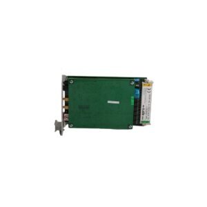
The Bently Nevada 991-50-XX-01-00, also cataloged as the 991 Thrust Transmitter, operates as a dedicated hardware component for axial position monitoring within rotating machinery protection systems.
Hardware Specifications
Parameter
Specification
Model
991-50-XX-01-00
Brand
Bently Nevada
Origin
United States
Weight
0.24 kg
Dimensions
81.3 mm x 61.2 mm x 103.4 mm
Operating Temp
-35 to 85 deg C
Power Consumption
24 VDC nominal (loop-powered)
Output Signal
4-20 mA proportional to thrust position
System Interface
3-wire proximity probe and extension cable
Mounting Orientation
DIN-rail or bulkhead mounting options
Machinery Monitoring & TSI Characteristics
The transmitter processes raw proximity sensor inputs and converts the physical gap into a stable 4-20 mA analog loop signal. During this process, the hardware validates the gap voltage, targeting specific calibrated voltage ranges to accurately measure axial displacement away from or toward the thrust bearing. Furthermore, the internal circuitry incorporates signal cross-talk suppression to isolate the transducer signal path from adjacent channel interference. Because the transmitter operates in direct correlation with eddy-current probe scaling, it translates minute micro-inch or millimeter movements into continuous data, which enables the main monitoring platform to perform real-time rotor dynamics evaluation and execute auto-shutdown logic when thrust limits breach safe thresholds.
Frequently Asked Questions
Q: How do technicians adjust the zero calibration on this transmitter?
A: Technicians establish the electrical zero by mechanically adjusting the physical proximity probe gap during machine standstill, which sets the target baseline voltage before loop operation.
Q: What happens if the extension cable breaks or disconnects during operation?
A: The transmitter detects the open circuit, drops its output loop current below 3.6 mA, and triggers a Not Ready or Fault status at the control platform to prevent false trips.
Q: Does this module require a separate power supply cable?
A: No, the device utilizes a loop-powered configuration; therefore, the same two-wire connection carries both the 24 VDC operating power and the 4-20 mA measurement signal.
Field Installation Guidelines
Mount the transmitter chassis onto a standard 35 mm DIN-rail or screw it directly to a flat bulkhead surface inside a weatherproof, environmental enclosure.
Connect the proximity probe extension cable coaxial connector securely to the transmitter terminal, then insulate the junction completely using silicone tape to block moisture infiltration.
Route the 4-20 mA field wiring through grounded steel conduit, keeping it away from high-voltage motor supply leads to prevent electrical noise induction.
Tighten all terminal block screw connections to a maximum torque rating of 0.5 N-m to guarantee continuous electrical contact without damaging the conductor cores.
Additional information
Weight
0.55 kg
Dimensions
32 × 16 × 20 mm
0.0
Average Rating
Rated
(0 Reviews)
Rated
0%
Rated
0%
Rated
0%
Rated
0%
Rated
0%
Be the first to review “Bently Nevada 991-50-XX-01-00 Thrust Transmitter Module” Cancel reply


0.0 Average Rating Rated (0 Reviews)