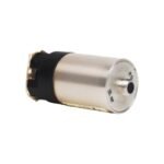
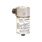
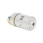
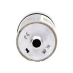
The 16699-10-02-01 is a premium passive moving-coil Velocity Seismoprobe transducer by Bently Nevada. Available Brand New as Original Stock with Global Shipping.
The Bently Nevada 16699-10-02-01 operates as a heavy-duty moving-coil velocity seismoprobe engineered to measure absolute casing and structural vibration on large rotating machinery. This self-generating passive sensor actively transforms physical mechanical motion into a high-accuracy analog voltage signal directly proportional to vibration velocity. Consequently, machinery health teams rely on this specialized transducer to execute continuous online condition monitoring on high-speed industrial assets such as gas turbines, steam turbines, centrifugal compressors, and large process fans. By delivering instantaneous mechanical velocity feedback, the device helps operators spot internal misalignment, mechanical looseness, and structural unbalance before severe fatigue triggers catastrophic failure.
Suffix Breakdown & Model Matrix
The part number sequence defines specific mechanical options and sensitivity ratings for the instrument interface. If your maintenance schedule dictates tracking specific variations, you can analyze the options via the standard factory breakdown matrix below.
-10 – Sensitivity Option: Calibrated for specialized high-sensitivity applications or specific omnidirectional calibration arrays
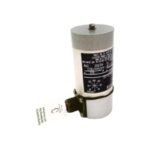
-02 – Mounting Configuration: Dedicated stud-mount setup using a 1/4-28 UNF mounting base
-01 – Connector Termination Variant: Standard military-grade top-mounted or straight MIL-style multi-pin electrical plug connection
Hardware Specifications
Parameter
Specification
Model
16699-10-02-01
Brand
Bently Nevada
Origin
United States
Weight
Approx. 0.32 kg (0.70 lbs)
Dimensions
2.50 cm Diameter x 24.20 cm Length (0.98 in x 9.53 in)
Operating Temp
-29°C to +121°C (-20°F to +250°F)
Power Consumption
Passive device (Self-generating electro-mechanical assembly, 0 mA required)
Frequency Response
4.5 Hz to 1,000 Hz (270 to 60,000 CPM) ±3 dB
Output Impedance
350 Ω nominal
Eddy-Current Probe Scaling and Gap Voltage Validation
Although the moving-coil architecture inside the 16699-10-02-01 operates independently of external power, its vibration data streams alongside proximity instrumentation that utilizes precise eddy-current probe scaling to verify dynamic shaft alignment. When technicians commission comprehensive protection racks, they execute a rigid gap voltage validation process to ensure adjacent proximity systems conform to standard -10 VDC targets within their linear spans. Setting this baseline target correctly ensures that the multi-channel protection matrix can correlate structural casing velocity data with precise rotor dynamics simultaneously. Furthermore, the specialized twisted-pair shielding applied during field wiring enhances internal cross-talk suppression. Consequently, this shielding prevents high-frequency inductive loops from bleeding noise into the low-impedance analog output of the velocity sensor.
Frequently Asked Questions
Q: Can a technician hot-swap the 16699-10-02-01 transducer connector while the machine protection panel is powered up?
A: Yes, because the sensor utilizes a completely passive, self-generating electrical design, you can safely hot-swap the physical MIL connector plug without damaging the internal coils. However, removing the sensor line will instantly break the signal loop and drop current to zero. Therefore, you must bypass the associated monitoring channel first to prevent the safety rack from triggering false machine trips.
Q: Does this velocity seismoprobe require external excitation voltage from a Proximitor or power supply?
A: No, this device functions as a passive moving-coil transducer. Mechanical casing vibration physically shifts the internal coil across a permanent magnetic field, which automatically generates its own proportional voltage output. Consequently, you do not connect external power rails to this module.
Field Installation Guidelines
Check Mounting Orientation: Always install the seismoprobe within its designated angular operating envelope, which requires strict alignment relative to the machine axis according to its specific directional code. Incorrect positioning offsets the internal moving coil and degrades measurement linearity.
Observe Torquing Limitations: Clean the 1/4-28 UNF stud mounting area thoroughly before attaching the sensor body. Secure the housing firmly using an industrial torque wrench, ensuring that you do not over-tighten the casing and stress the internal permanent magnet assembly.
Implement Single-Point Shielding: Connect the braided shield wire of the twisted-pair field cable exclusively at the terminal block inside the monitoring enclosure. Concurrently, isolate the outer shield at the machine casing side to avoid establishing ground loop currents.
Provide Physical Cable Strain Relief: Secure the flexible conduit leading from the top MIL connector to the structural machine frame. This relief layout stops continuous high-amplitude casing vibrations from fatiguing the electrical pin connections over long operating campaigns.
Additional information
Weight
0.78 kg
Dimensions
40 × 70 × 100 mm
0.0
Average Rating
Rated
(0 Reviews)
Rated
0%
Rated
0%
Rated
0%
Rated
0%
Rated
0%
Be the first to review “Bently Nevada 16699-10-02-01 Velocity Seismoprobe Transducer” Cancel reply


0.0 Average Rating Rated (0 Reviews)